Acoustic Bass Guitar Case
Quick links:
Materials Trapezoid = corners <> 90 degrees Cutting plywood pieces Commence construction Hinge and latch cutouts Making the heel-barrier Starting the neck-support piece Starting on the cushions Completing the neck-support piece Lid cushions Final steps
Overview:
There are no commercially available cases or gig bags that will fit my acoustic bass guitars
Length |
1240 |
49" |
Lower bout |
460 |
18" |
Depth |
155 |
6" |
This trapezoidal case is rough'n'ready, a little heavy at 13.3kg, but should give good protection.
Since I can't buy materials and components in bulk, it's not exactly cheap. There's also lots of
hard, sharp edges that dream of damaging your guitar in a way that a gig-bag, or even a fully-lined
bent-plywood case wouldn't, but if you're careful loading and unloading you should be able to avoid
those kind of disasters.
Videos
I've made two YouTube videos on this build process:
Trapezoidal bass flight-like case, design scribblings
Need to be adjusted to acommodate thickness of plywood & foam
Initial sketch |
Measured |
(interior dims, 25mm clearance) |
|
overall length: |
1270 |
~1255 |
(1253 from Pythagorus) |
width at body-end: |
560 |
570 |
|
width at headstock-end: |
160 |
160 |
|
side length: |
1286 |
1270 |
|
depth: |
215 |
(20mm clearance at bottom, 40 at top) |
|
deviation angle: |
8.95 |
9.21 |
|
body-end angle: |
81.05 |
80.79 |
|
headstock-end angle: |
98.95 |
99.21 |
this seems to work for my basses having 160mm body depth at deepest point
use the body-thickness "calipers" jig - gently - to make sure bass is approximately this thick
Deviation angle calculation (after measuring)
body_width - headstock_width: |
410 |
half that ("rise") |
205 |
hypotenuse |
1270 |
"run" (Pythagorus) |
1253 |
rise / run |
0.1636 |
arctan (radians) |
0.16076 |
degrees |
9.21 |
"Discrete" foam inserts / components
Stiff grey foam
29-400, available in 25/50/75/100, quite expensive
Softer black foam
"fuel filter foam" (can be ordered from Titan AV, cheaper)
Fat = 50mm
Thin = 25mm
Heel-barrier (stops body from moving towards headsock end)
Neck cradle (supports neck pushing upward_
Fat bottom (on bottom, across heel, part of upper bout)
Thin bottom (on bottom, across rest of body)
2x Fat sides (on sides, at upper bout / waist)
2x Thin sides (on sides, at lower bout)
2x Thin ends (on end-side, split for benefit of strap button)
3x Fat top (on lid, two along each side of body, one at end past bridge)
Thin top (on lid, along middle, bridge to nut)
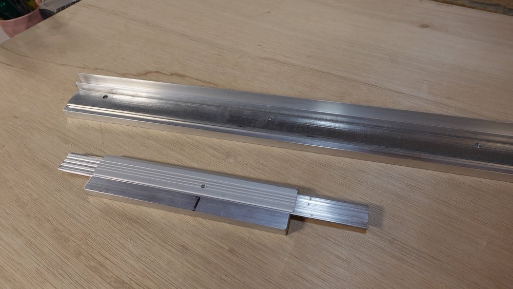
Materials
Current working approach: double angle joiner extrusion
6mm / 0.25" plywood to keep weight down
Angle channels mean sides stop before the corner ("symmetrical" corners rather than butt joints)
With this hardware each piece needs to be 3mm LESS than the target interior dimension
(1.5mm offset in joiner cross section)
Rather than building the carcase and then cutting the lid off,
We'll build box and lid separately.
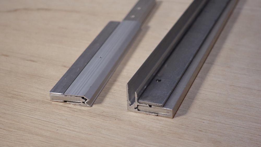
The hardware for this build, square-interior hybrid tongue-and-groove channel adds 6mm to height
5mm at "outer overhang" side (lid)
1mm at "outer bevel" side (box)
NB: double-check all of these, part numbers / options etc.
Supplier |
No |
Part |
Description |
Penn Elcom |
2* |
L978/928SMOL3 |
Medium SMOL3 Recessed Latch in Deep Dish with 22mm Offset |
Penn Elcom |
4* |
L0906 |
Backplate for Medium Recessed Latches |
Penn Elcom |
1* |
H7159EZ |
Heavy Duty Medium Zinc Recessed Handle with Rivet Protection |
Penn Elcom |
1* |
H1906 |
Backplate for Medium Recessed Handles |
Penn Elcom |
3* |
P2598Z(P2597Z) |
Medium Lid Stay in 7mm Deep Dish with 30mm Offset (prefer smaller offset) |
Penn Elcom |
2* |
E0885-2M |
6.8mm Double Angle Extrusion with 30mm Legs - 4m Long (prefer 4* 2m Long) |
Penn Elcom |
8* |
B1128/01 |
6 Hole PennBrite Brace with Offset 51.5mm x 42mm |
Armour |
2* |
EH6 |
ALUMINIUM HYBRID EDGE EXTRUSION, 6MM GAP |
Titan AV |
5* |
SKU: RC-SP-RIVET5-18S |
5x18 Aluminium Rivet & Washer, Silver, 100pcs |
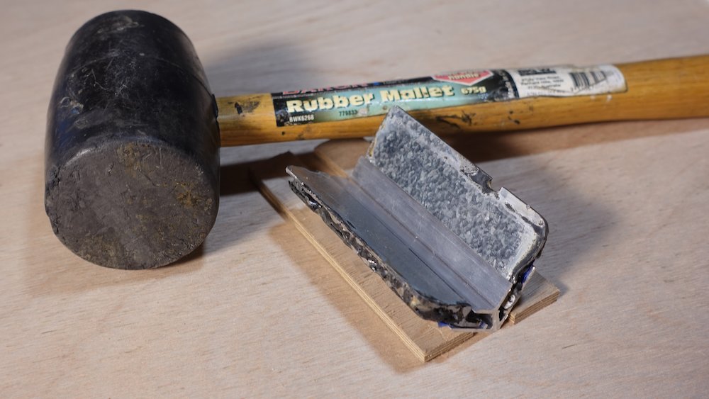
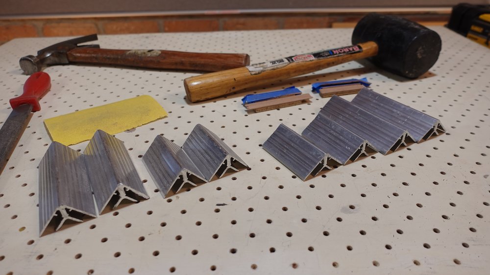
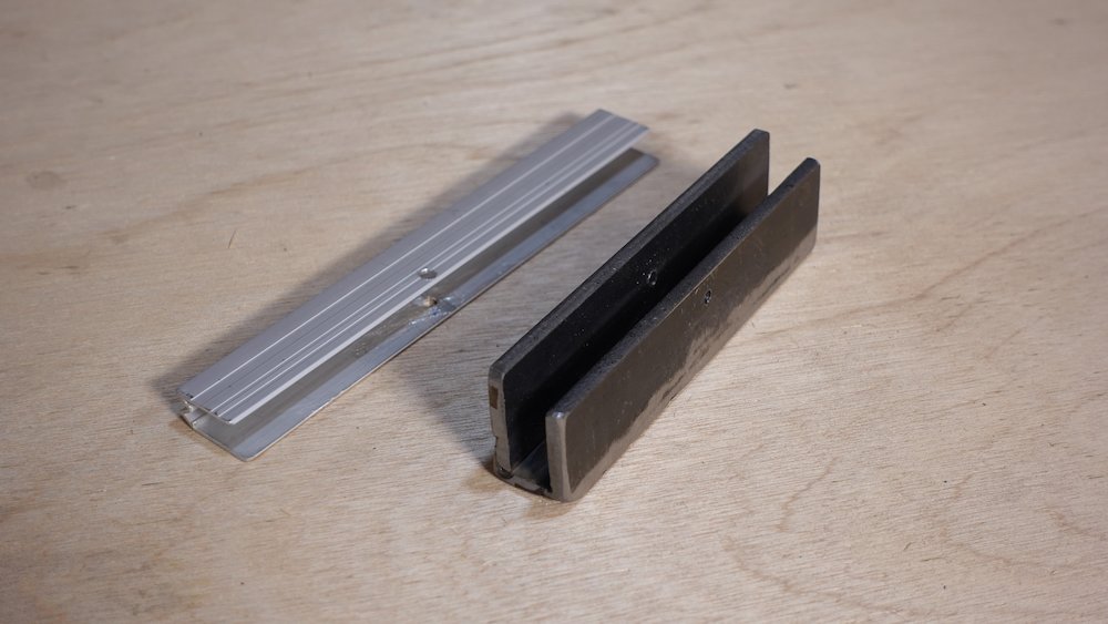
Trapezoid = corners <> 90 degrees
Using the spreader and smoosher anvils, hammer and corner punches, bludgeon the hardware pieces into submission.
These jigs take a corner-piece, or length of corner-joining section, and adjust the angles.
The spreader fits inside a 90-degree angle, and by way of hammering the outside, spreads it to 99 degrees
The spreader allows a 90-degree angle to nestle inside it, and with a series of punches, compresses it to 81 degrees
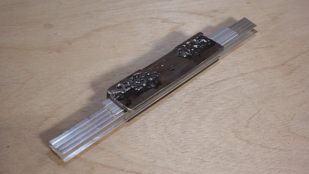
Update
To reduce damage to double-angle joiner uprights I've made two further developments:
A bent 1.5mm sheet metal insert for the smoosher jig, which protects against the roughly-ground weld beads, significantly reducing scarring.
Two horribly-welded and masking-tape-shimmed inserts for the spreader jig, which when coupled with using a rubber mallet, eliminate outside damage (inside is still scarred)
The spreader jig |
The smoosher jig |
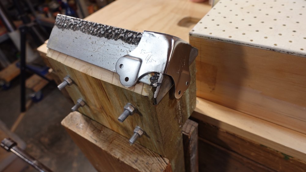
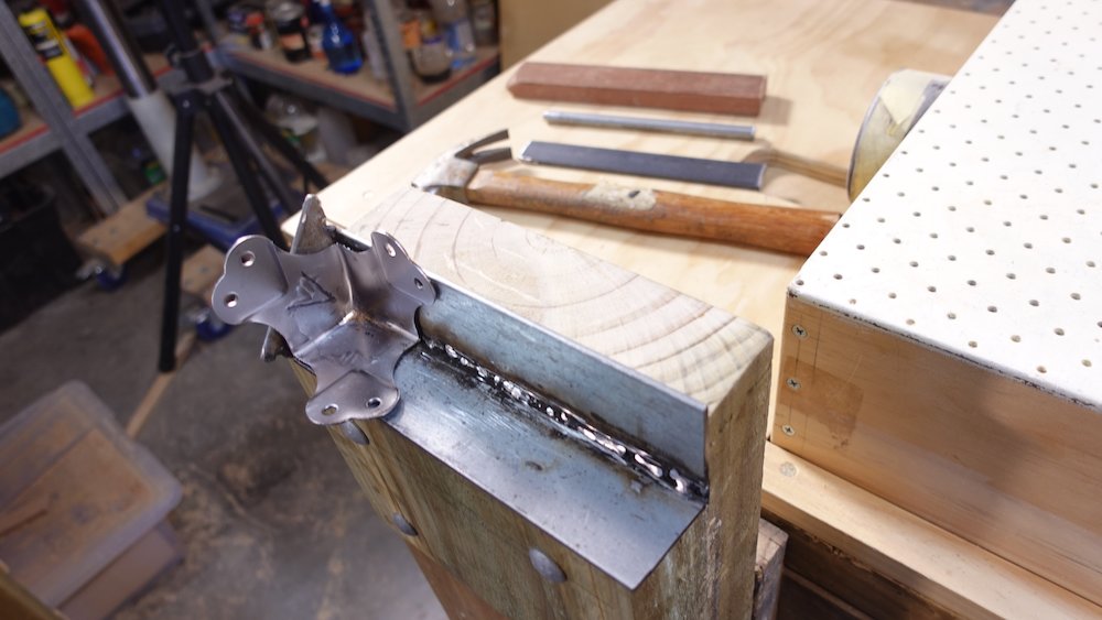
Smoosher lining for aluminum uprights |
Inserts for spreading aluminium uprights |
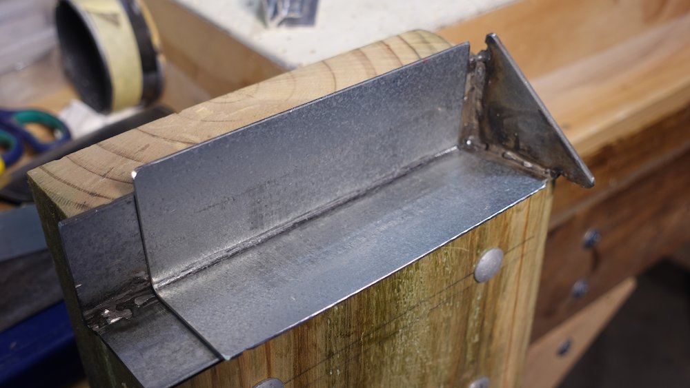
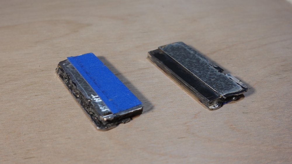
Inserts, um, inserted |
Aluminium uprights showing less scarring |
Cutting plywood pieces
Trace two copies of trapezoid from MDF template onto 6mm ply sheet
For a target interior body length of 1260mm, but remember we subtract ~20mm for (2x) joiner section overhead
This will give something like
interior body length: |
1257mm |
side length: |
1274mm |
width at body: |
164mm |
width at headstock: |
573mm |
Cut these two pieces out, clamp together and plane edges straight and true
If there is any asymmetry, clearly mark which side is "up" on both pieces
After various calculations and builds, our default base and lid piece heights are 127 and 82mm respectively.
127+82 = 209
tongue and groove adds 6mm (=215..)
(There is an small additional contribution from the way pieces fit into corner channel)
Side pieces therefore should start out as
Piece |
Number |
Size |
Lid sides |
2 |
1274 x 82mm |
Lid body end |
1 |
574 x 82mm |
Lid neck end |
1 |
164 x 82mm |
Box sides |
2 |
1274 x 127mm |
Box body end |
1 |
574 x 127mm |
Box neck end |
1 |
164 x 127mm |
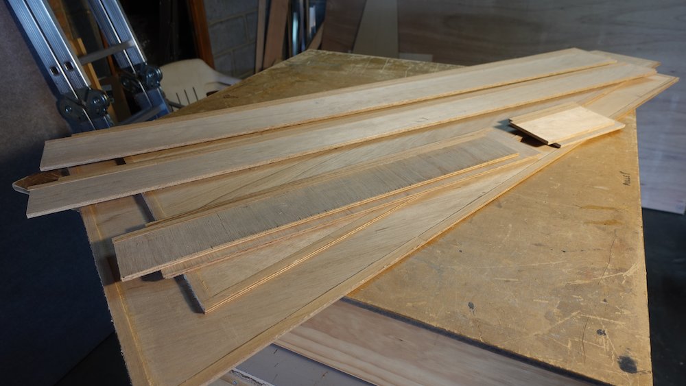
In this build I could only find 6mm tongue-and-groove, and ~7mm double-angle joiner section,
so I glued strips of shim veneer to the pieces.
Experiments have proved this necessary: rivetting closes the gaps, but the resulting angle is not 90-degrees.
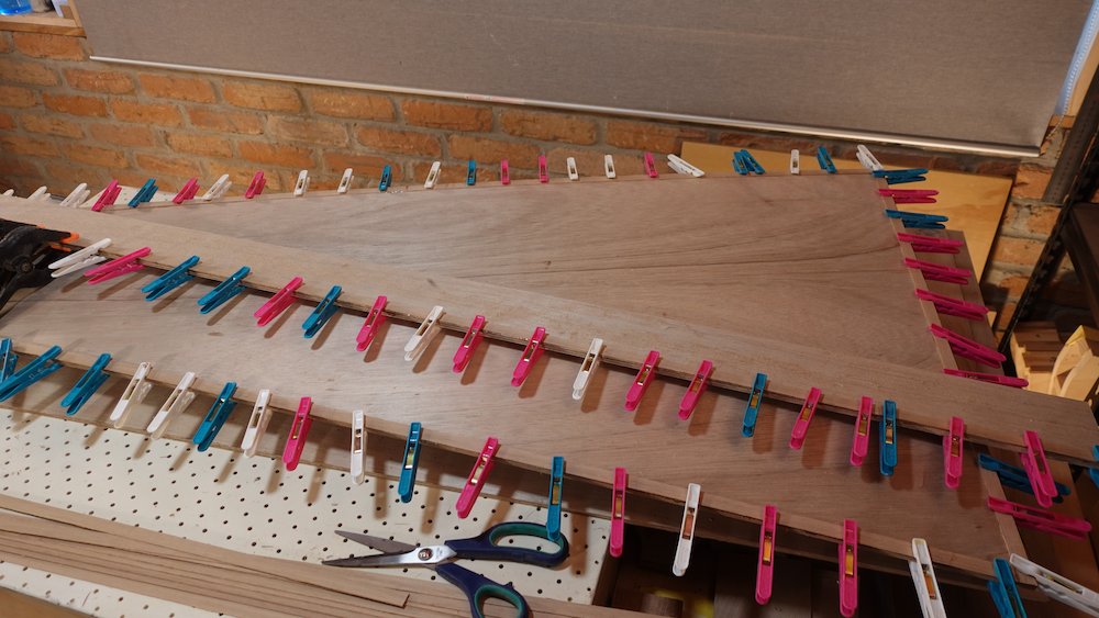
Glue to all pieces that fit into double-angle joiner section
Titebond (and other water-soluble glues) may cause the veneer to curl, making clamping difficult. Polyurethane glue doesn't have this effect, but you really have to use a tiny bead or squeezeout is an issue.
For the vertical edges of sides, the veneer strips will interfere with the tongue-and-groove section. Either measure / stop short, or leave it to chiseling later.
Actually, it's more complex: on the body-end, where the upright section is smooshed to 81 degrees the veneer padding is not even required.If top and bottom are asymmetrical, this is where we must commit to orientation
Two options:
Mill strips to <1mm, glue and hope for the best
Mill strips to >1mm, glue, thickness with drum sander
(which is just wide enough for wide end of top & bottom pieces)
Cutout template
Simplify cutout process by making hinge, latch and handle cutouts now instead of later
NB: it is critical to label each side piece: inside/outside, head-end/tail-end, even base/lid, so that when marking cutouts using the template, they're all in the correct location.
NB: note that the cutouts for non-offset hinges are not vertically symmetrical, even though the hinges themselves are.
This is to account for how tongue-and-groove channel shifts the apparent join line when the taller lip is outward-facing on the lid and inward-facing on the box/base.
Side piace cutout diagram / template |

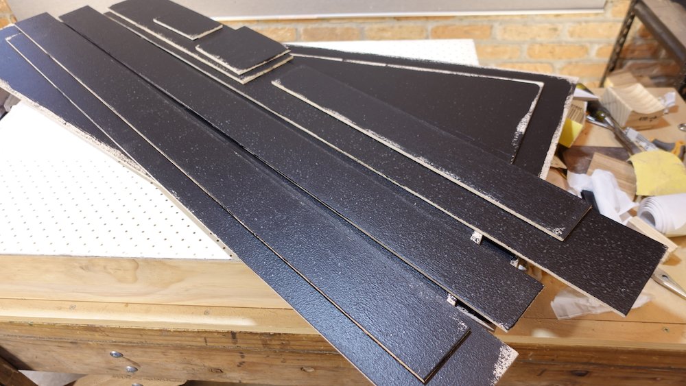
Paint the inside faces with black water-based enamel, semigloss/satin ideal, (don't need to go to the edges)
Finish the outside faces with Duratex: one brushed-on layer, one or two coarse-sponge-roller'd
To save on Duratex
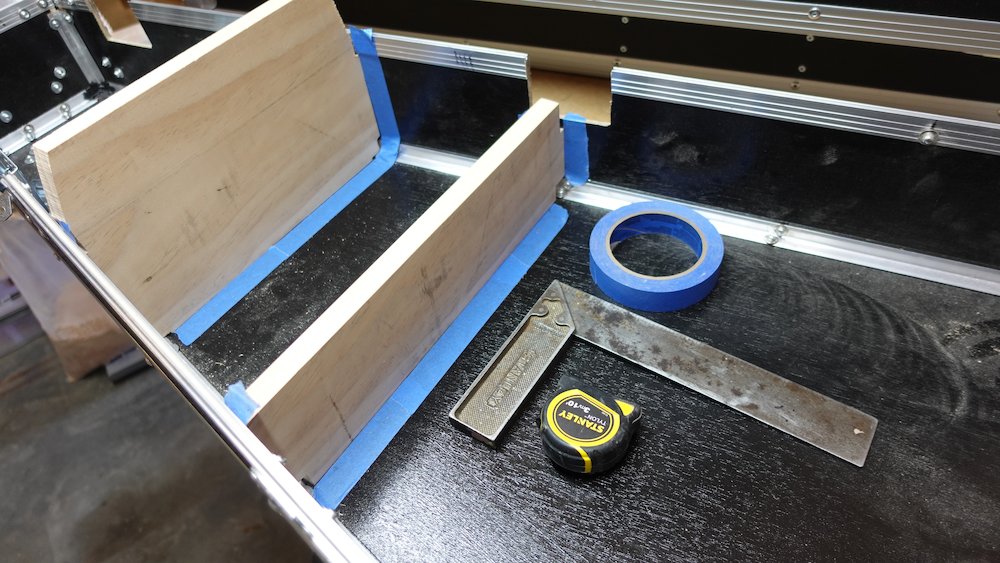
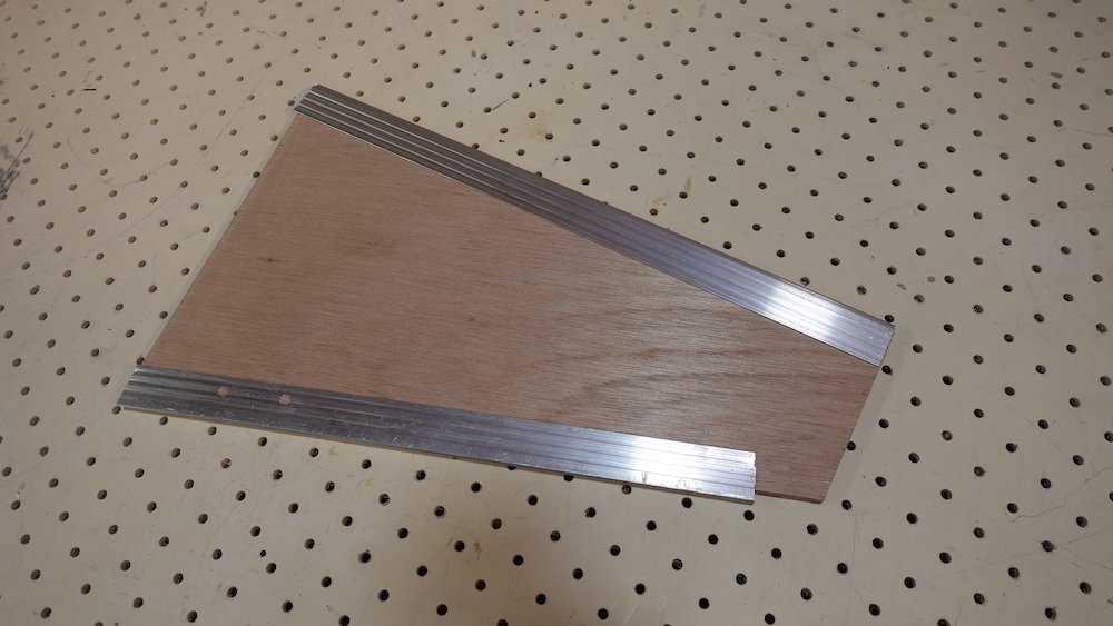
Consider building neck-support piece (actual width-bevel can be finessed later)
Then we can finish the exposed parts now (see images below)
Attaching edge-padding strips |
Edge-padding strips attached |
Painted plywood pieces |
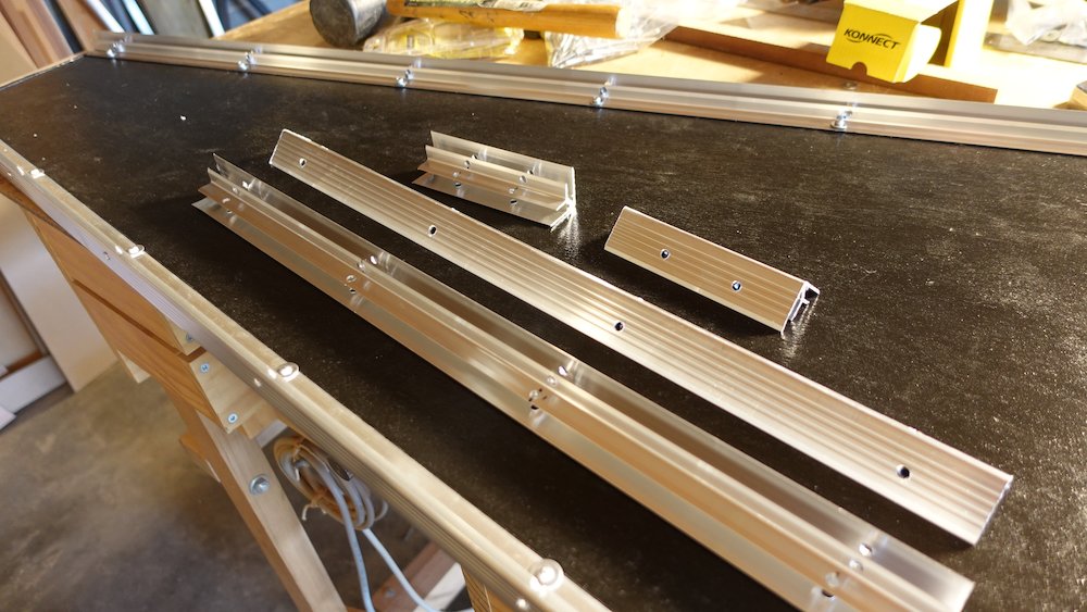
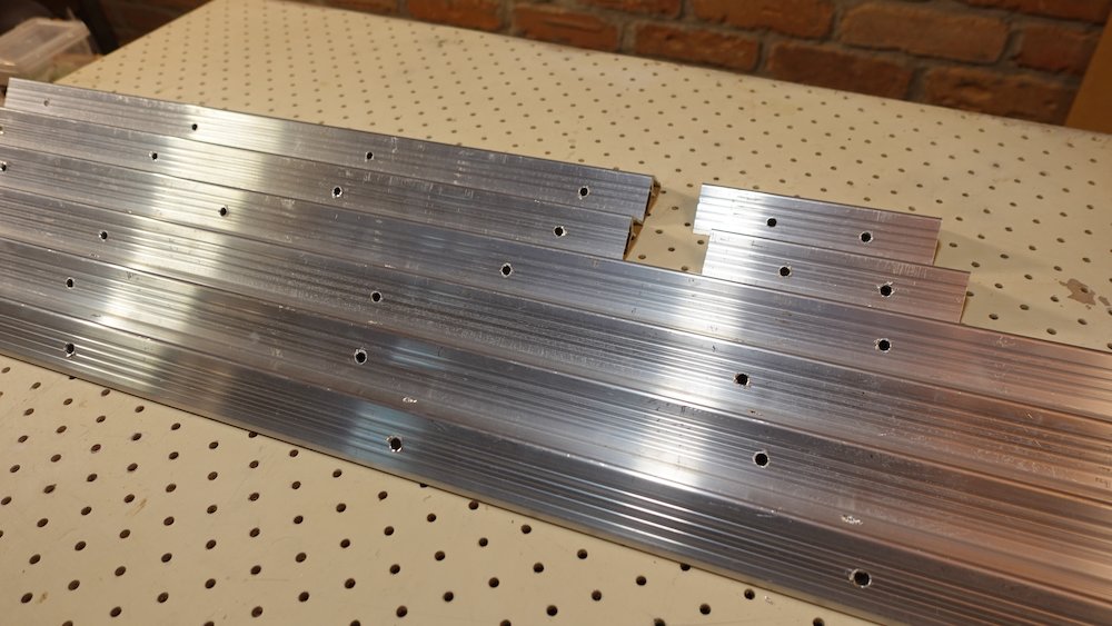
Cut pieces of angle-joiner section |
Commence construction
Drilling guide for double-angle joiner section
Long guide, so we can use it for hole spacing/offsetting as well as transverse position guide
Exterior piece is 3mm steel
Interior support piece is 6mm aluminium stock with cladding made from 10x20mm box section, cut lengthwise so one leg is max, the other 12mm
Drilling guide for double-angle joiner and tongue-and-groove sections
Shorter piece for drilling individual holes
Exterior piece is actually 9mm tongue-and-groove section, which allows 6mm section to nestle inside
Interiour support piece is 6mm stock with cladding from cut 10x20mm box section
The guide hole is positioned in the first narrow valley of the short leg of the 9mm section
Drilling guide pieces |
End view of support pieces |
Stock loaded into drilling guides |
End view of loaded drilling guides |
Cut long lengths of double-angle joiner 40mm short of trapezoid pieces (to leave 20mm clear each end: ~1234mm)
With double-angle joiner we cannot have rivets at the same position opposing each other
we must either offset them minimally (5mm) or in some sort of alternating arrangement
for seven rivets each side, ending ~40mm in from each end of cut aluminium (~60++ in from trapezoid piece ends)
7 rivets = 193 spacing
Drilling technique:
drilling will tend to enlarge template holes
use template to drill starter holes only
when a piece or set is done, drill all the way through using internal support piece only
Follow same procedure for trapezoid end edges
channel 40mm shorter than edge (~534 & 124mm)
rivets starting 35..40mm in from edge, each pair offset by 5mm
The following measurements from LHS edge give decent offsetting:
wide end: 40, 190, 340, 490
short end: 35, 85
Attach all perimeter channel lengths to trapezoid pieces (including rivetting)
Cut corner-edge lengths for verticals
Lid: 4x lid plywood height-38, eg 89mm if 127
Base: 4x base plywood height-36, eg 47mm if 83
Note: in previous builds we made these ~15mm taller, but they interfered with the horizontal joiner pieces and needed to be notched.
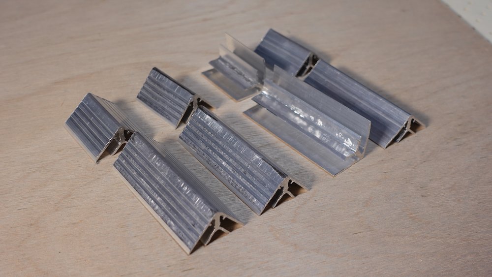
Use the spreading and smooshing jigs to fit the +9/-9 degree trapezoid angles
Put some plywood scrap in the channels to assist in distributing force from one side of channel to the other
Note that for spreading, some additional padding will be needed to transfer jig geometry to piece
Also, for smooshing, the jig will damage the aluminium finish, this can be legitimised by sanding and filing (update: much less severe now, see notes at top)
Joiner section pieces drilled |
Vertical joiners spread and smooshed |
Mallet in all side pieces but don't drill through the joiner-channel holes yet
Hammer in the angle-adjusted vertical channels from the open end
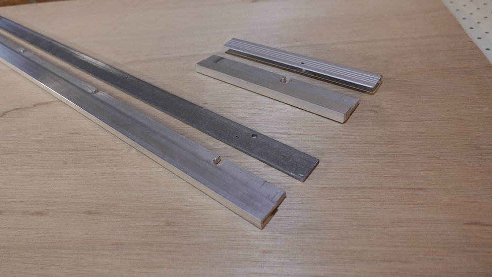
Cut tongue-and-groove channel pieces, bevelling ends with band sander (to account for 81/99-degree angles), mallet them in place
Sequence
Cut the four long lengths a few mm oversize
Mallet them in place
Position lid on top of box
Slide/adjust so that lid is mating perfectly with base
Measure the two end lengths, taking note that the bevels are internal
Do the bevels on the band sander, hammer them in place
Check that lid fits
Mark external bevels on the (still oversize) but don't sand them yet
Label all tongue-and-groove channel pieces so we know where they go
While they are still fitted, and with the lid fitting perfectly, mark all rivet holes as follows
Lid, front side:
Two, 530mm in from each end (corner brackets & latches will provide the rest)
Base, front side:
One, 530mm in from left/headstock end (ditto plus handle)
Base and lid, back side:
Two, 380mm in from each end (corner brackets and the three hinges will provide the rest)
Base and lid, wide end:
Two, 200mm in from each end
Base and lid, narrow end:
(nothing, corner brackets are enough)
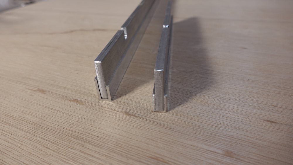
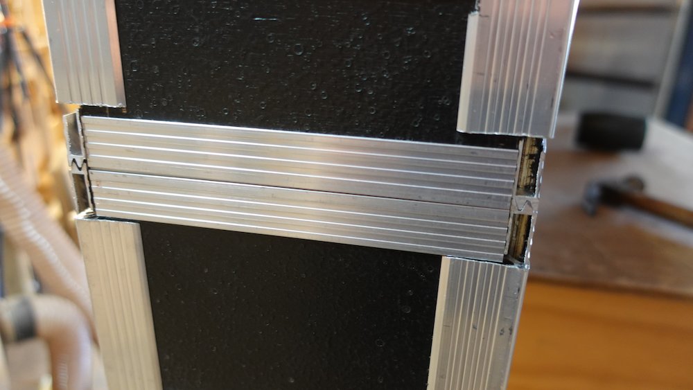
Remove tongue-and-groove pieces and drill rivet holes where just marked, using a drilling guide:
6mm tongue-and-groove channel nestles perfectly into 9mm tongue-and-groove channel
(but guide holes in almuminium will enlarge over time)nestling all that inside a custom steel U-frame will greatly reduce that problem
(ugly welding but adequately fit for purpose)
Two-piece lip drilling guide |
Lip channel nestled in drilling guide |
Cut or sand (just outside) the remaining external bevels on the four long pieces
Refit the tongue-and-groove pieces, clamp up, make sure everything is fully seated
File the external bevels so the outside perimeter it clean and tidy
File an additional small round-over so they can be covered by the eight lip-corner braces
More important at the sharp body-end corners than the headstock end
With base and lit clampted together, drill all holes through the wood - double-angle joiner section and tongue-and-groove lip section
Drill one or two pilot holes for four of the eight lip-corner braces (eg, all the lid pieces)
Unclamp, take off lid, rivet remaining double-angle and tongue-and-groove channel holes
Fit corner braces with single pilot rivet, reclamp, drill remaining corner brace holes, rivet
Clamp again, drill four pilot holes for remaining corner braces (nestle them against the rivetted ones in the lid)
Unclamp, rivet, clamp, drill remaining holes, unclamp rivet
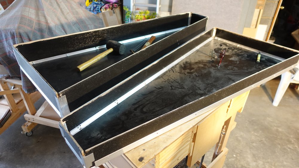
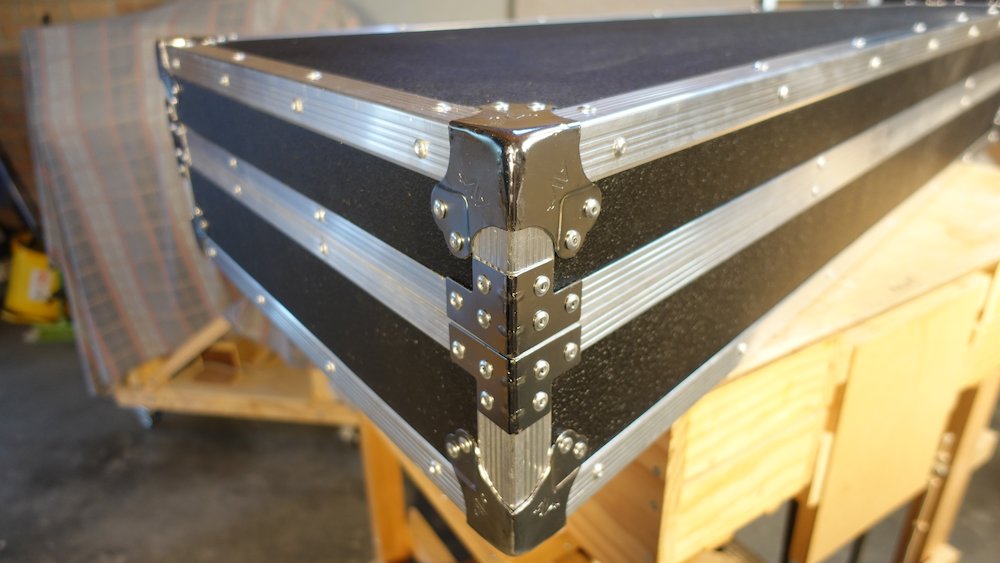
Moment of truth: check that the lid fits!
Sides assembled |
Checking alignment |
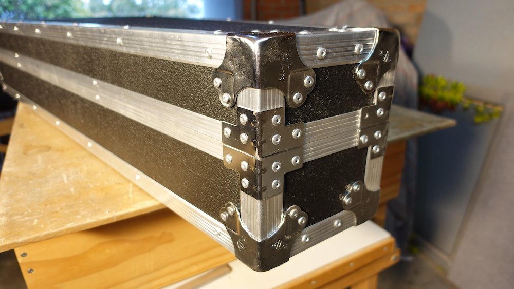
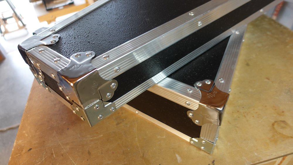
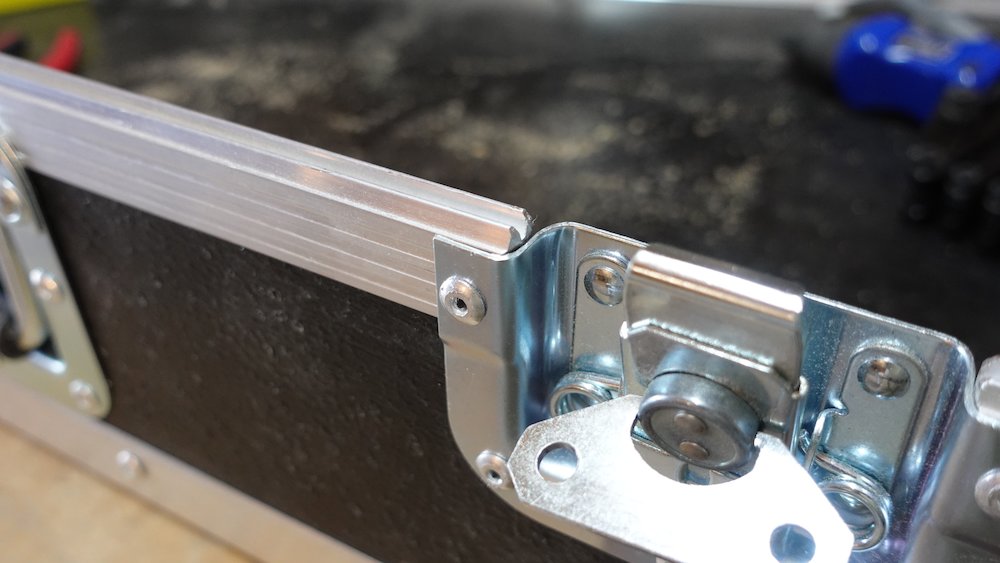
Fit corner pieces:
Assuming the pieces are correctly angle-adjusted:
Drill holes while holding each piece in place
Minor "tilting" may be required, which should increase rivet tension
Rivet in place
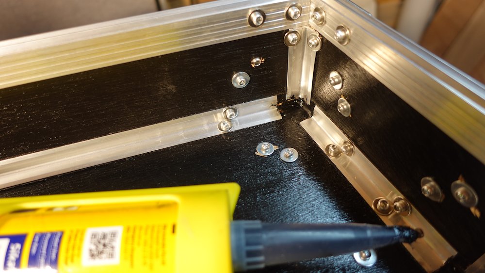
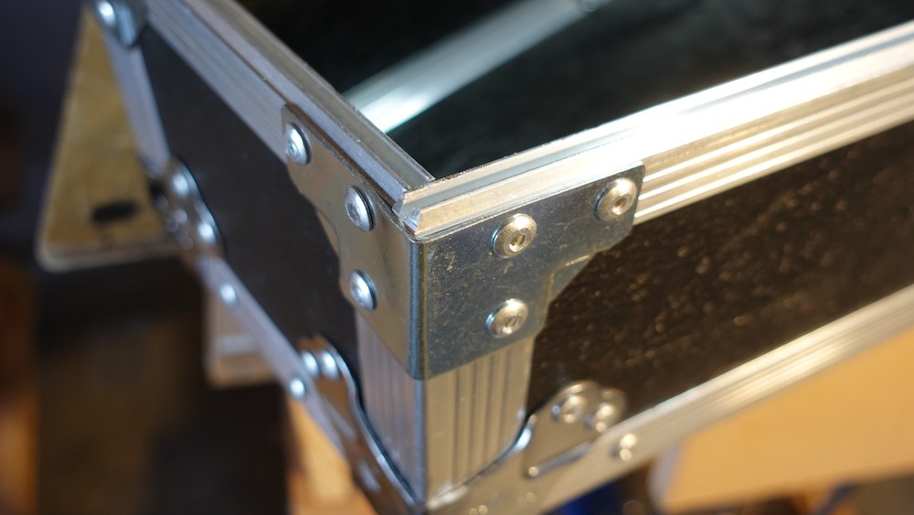
Waterproofing measures
there's quite the gap around each corner, and the 3-way corner pieces aren't a watertight fit
glue-gun some silicone sealer into corner cavity (black Sikaflex) to improve water resistance
Brackets fitted |
Completed corners, headstock end |
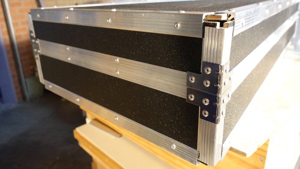
Completed corners, body end |
Sealing interior corners |
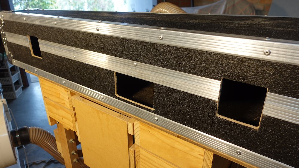
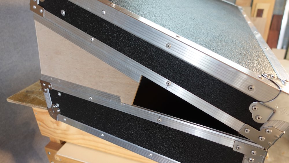
Hinge and latch cutouts
NB: if the playwood already has these cutouts some of the notes below won't apply.
In that case, cut away any pieces of tongue-and-groove channel covering them, and skip to steps X and Y in Procedure, below.
Time to cut and drill for hinges, but do not attach yet
We're using three, so the hinge-stay stresses are borne right next to the corner brackets
The two outer ones are as close as possible to the edge (leave 5mm gap from bracket)
The one in the middle is a potential problem, as it is right where we need the heel-barrier to be,
which also functions as a through-brace giving support to the handle.Therefore, the middle one should sit 530..630mm measured from the wide-end outer corner
(symmetry is overrated, lol)Current hardware:
Width |
102mm |
Cutout width |
73mm + bevel |
Cutout depth (lid) |
24mm + bevel |
Cutout depth (box) |
50mm + bevel |
Cutout depth (non-offset) |
37mm + bevel |
Surround offset |
14mm |
NB: cutout depth for box is measured from the tongue-and-groove outer-ledge, not the highest point!
Start cutout so that entire 18mm in from ends of corner brackets
Start smaller, enlarge by bevelling
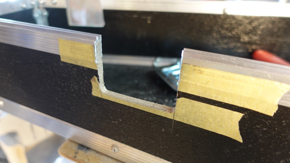
Procedure:
Drill corners
Step X: Cut aluminium with angle grinder, finish with hacksaw
Cut verticals with pull-saw
Rough-in horizontals with jig-saw
Step Y:Smooth aluminium with rasp
Smooth wood and enlarge/bevel to fit with Shinto saw-rasp
Again, do not attach yet
Repeat similar procedure for latches:
Current hardware same dimensions as latches
However, we only fit two, cutouts starting 250mm from each end
Don't fit them yet, the holes will make fitting hingers a lot easier
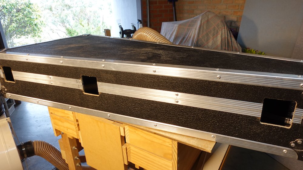
And finally again for the handle:
Centre hole approx 763mm / 537mm in from the neck/tail ends respectively
Vertical placement: align the top of the cutout with the bottom of the tongue-and-groove channel
Current hardware, hole should be 125 x 70mm
That means hole should extend from 20mm..90mm above top of bottom channel
Cut hole a little small, enlarge with file/shinto to get perfect position
Might as well fit it at this stage
Corners |
Cutout |
Holes cleaned up, front |
Holes cleaned up, back |
Bevelled lip ends |
More bevelled lip ends |
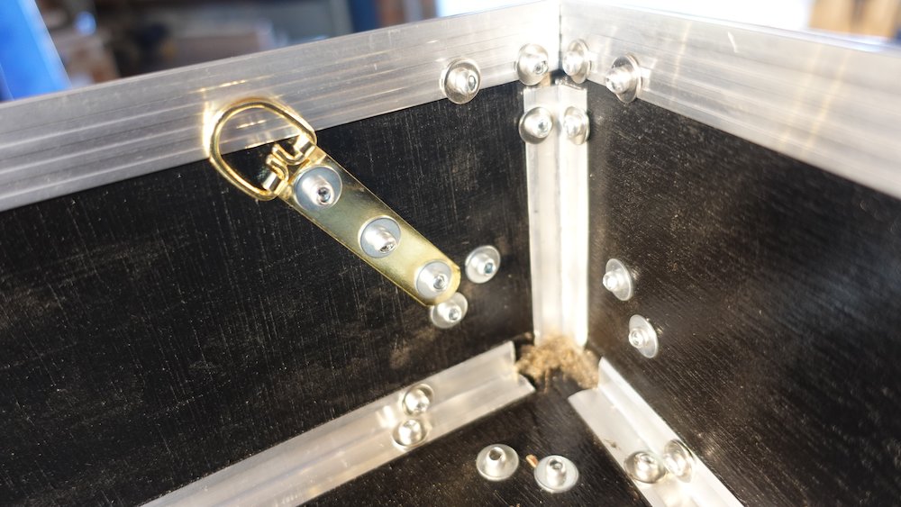
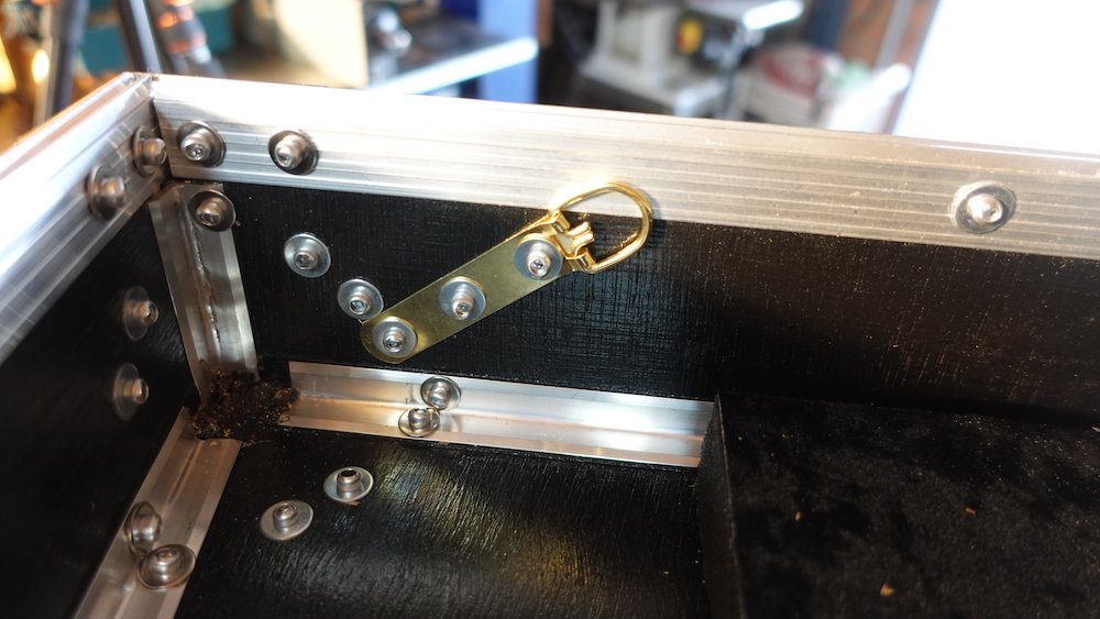
Fit anchors for cord-lid-stay (fit heavy-duty picture anchors with rivets)
Lid: approx 90mm from inner RH-front corner
Base: approx 65mm from inner RH-front corner
Cord stay anchor (base) |
Cord stay anchor (lid) |
Making the heel-barrier
Cut heel-barrier timber, ~370 x 100, with bevelled sides so it fits upright
Inward-facing edge about 625 from inside of wide end.
(This would have been where the middle hinge sat, had we centred it prefectly)
Cut 16x16 cutouts in the bottom corners, to avoid aluminium channel and rivets
Cut bevel on tablesaw, with about 50mm rise over 300mm
finalise fit, making sure that piece is perpendicular to centreline
check that we're not making sides bow outward (interfering with lid closing)
However, since we'll be screwing the piece in, we don't want it pulling the sides inwards either
mark outlines on bottom and sides
drill screw holes from inside, countersink from outside
holes are best positioned if drilled from the inside,
however this can cause a lot of unwanted blowout on the other (already painted) side.
Either use a sacrificial backing piece, touch-up the blowout with paint,
or attempt to transfer measurements to the outside and drill inwards.don't screw or glue it in yet
Starting the neck-support piece
Cut neck-support piece using same plan, but don't finalise height yet
190mm tall in the middle, height/shape to be finalised later
Width to fit 200mm tailward of heel-barrier cushion piece (310++mm a good start?)
At edges, trim so it clears tongue-and-groove channel
again, don't fit it!
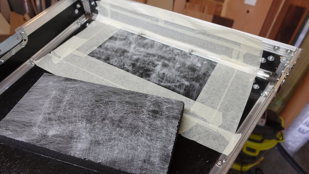
Starting on the cushions
When attaching velvet to foam:
adhesive overspray is impossible to cleanly remove from foam
mask off any foam surface that will be exposed
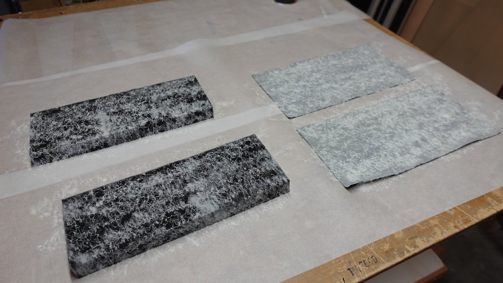
Cut main base body cushion
25mm foam, use trapezoidal template, extending 540mm from tail toward heel
will stop short, to be filled in with thicker piece after fitting heel-barriercut a piece of velvet slightly overside, glue together, trim fabric flush
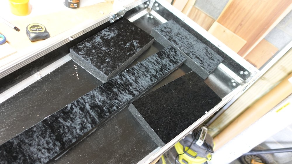
Cut two base tail cushions, and two base lower bout cushions
25mm foam, ~287mm long, ~108 high
2* the harder stuff (tail) and 2* normal (lower bout)
cut maching pieces of velvet
all pieces have wrap over the top
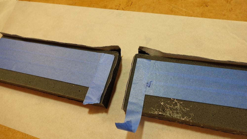
for tail cushions, also wrap over the inner join, so strap button won't catch on trimmed edges
Cut heel-barrier cushion
harder foam, about 280x380, to wrap around the heel-barrier timber, edges flush with base
mask off barrier base and sides to prevent glue residue (which will interfere when we attach it)
attach foam, trim to fit, then wrap with velvet & trim again
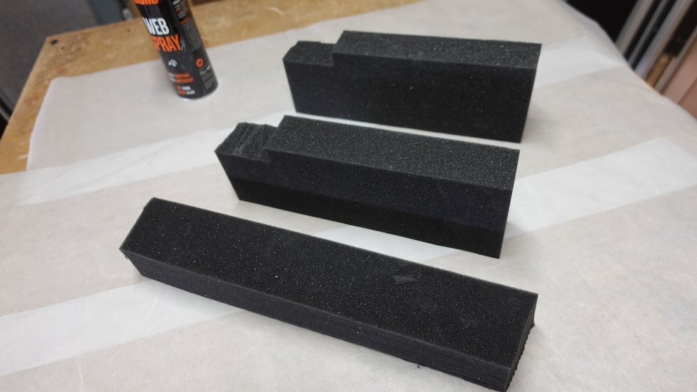
Nestle all pieces (so far) in place, measure and cut the tree thicker cushions
1x heel-base cushion, approx 400x70mm (bevelled to fit)
2x upper bout cushions, will be approx 300x105, with a cutout to clear the heel base cushion
cover with velvet
Fitting supports |
Gluing velvet |
Tail cushion fold-over technique |
Tail cushion before secondary gluing |
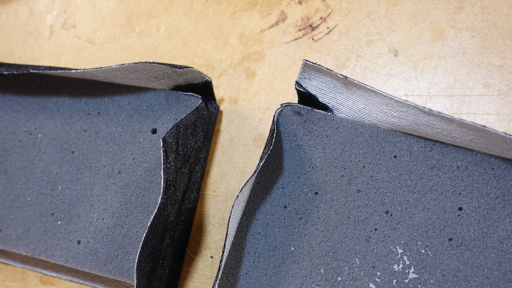
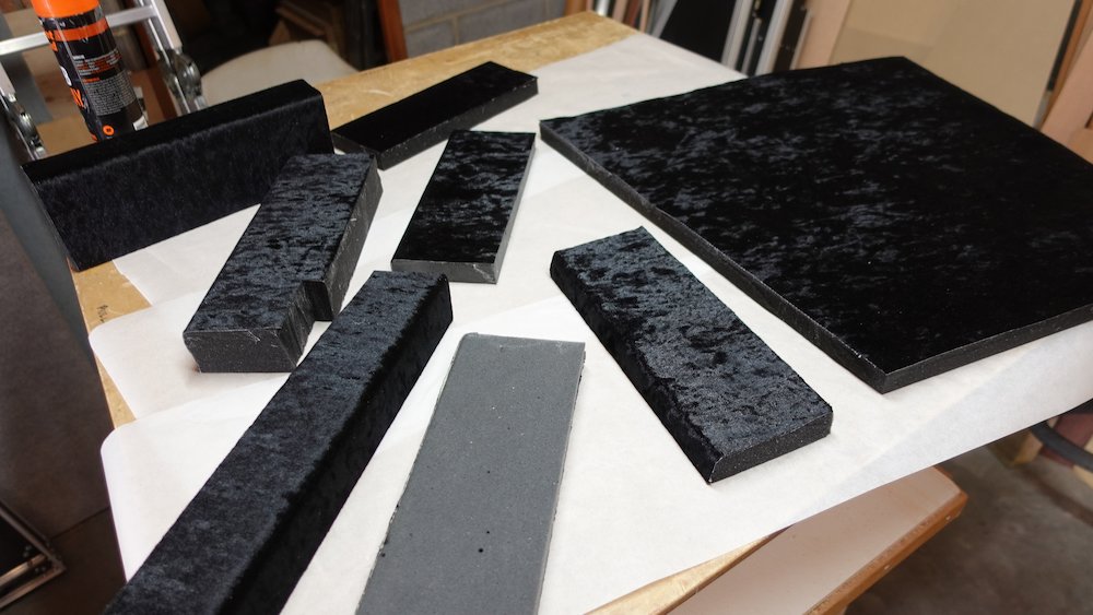
Thicker lower-bout cushions |
Some covered cushion pieces |
Trimmed heel stop before velvet |
Completed heel stop |
Completing the neck-support piece
Nestle all pieces in place again, plan height of neck-support
put guitar in padded case bottom, check neck is horizontal
put a padded shim under headstock if required
measure from base to underside of neck (expect approx 170mm)
transfer this measurement to neck support piece
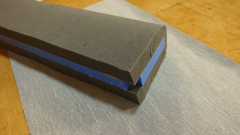
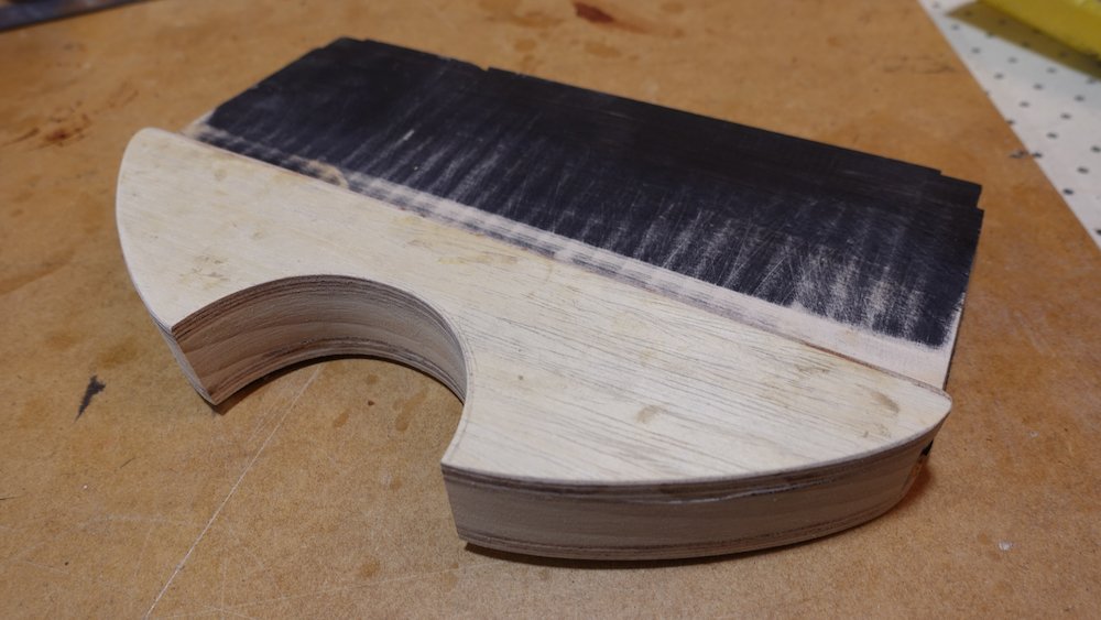
Designing neck-channel profile (see image below)
mark actual position of neck-bottom on incomplete neck support piece
centre this, then mark 23mm (25mm foam, slightly compressed) below that
draw a 50mm radius / 100mm diameter circle that touches this point, above it
mark a point 42mm above the lowest point of the circle
using a 13" or 14" cymbal as a guide, trace from sides to this 42mm point
(this is another way of saying "the top perimeter ends about 190mm up from the base")the larger circle should extend up from the lip-edge of the case bottom, to the top of the piece
the smaller circle should cut into the larger (when padded with foam, it is the neck pocket)
cut just outsite these lines roughly on the band saw, get closer on the band sander
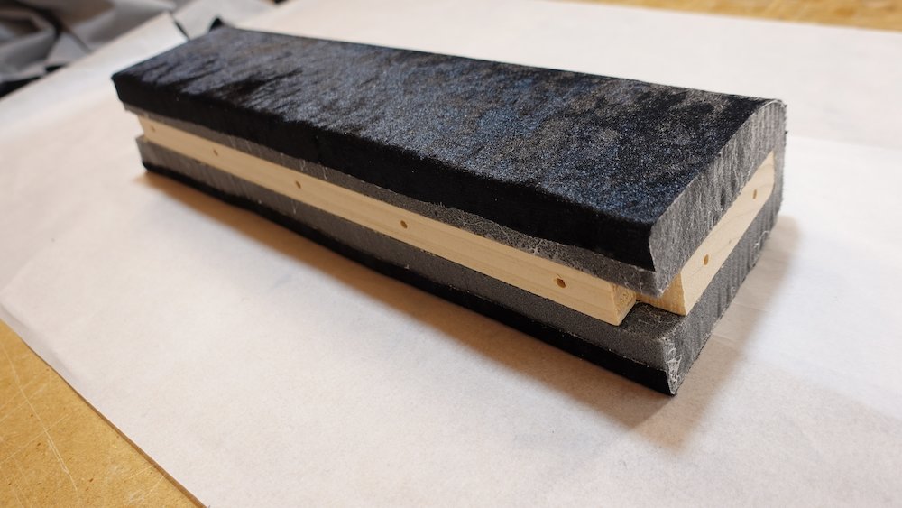
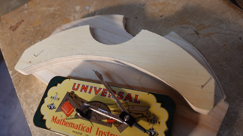
Completing neck-channel support piece
trace the outline on some pieces of 9mm plywood, so channel portion will be thicker
decide how far these widening pieces go down: flat, aligned with tongue-and-groove, scalloped upwards, etc
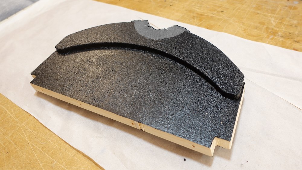
A 22" cymbal is useful for the scalloped underside curve, see images
cut the extra pieces, glue to main piece
finalise profile with band sander spindle etc
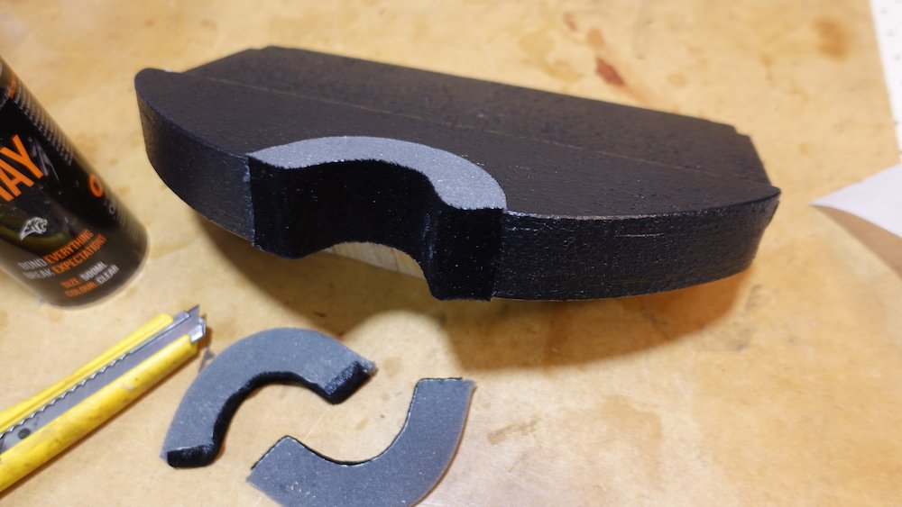
paint the piece black: textured finish on exposed surfaces
glue 25mm foam in channel
glue velvet over exposed foam channel faces
trim edges
Nestle completed neck-support in place, check strings are level lenghth-wise
hopefully, strings section will have correct clearance for 25mm foam
Neck-support before cushion |
Neck-support complete |
Scalloped neck support mid progress |
Scalloped neck support completed |
Lid cushions
Cut, measure, and resaw to correct thickness
one 25mm piece, 900x90mm (bridge to nut)
cut three 50mm pieces, 150x300mm, two positioned either side of strings, one between bridge and tail
They will almost certainly be too thick: rest lid in place, measure how far off closing the lid is, then resaw to correct thickness with bandsaw!Cover with velvet, glue into the lid using low-tack masking tape to protect borders from overspray
Do a test-fit of both heel-barrier and neck-support pieces
screw them in, then test that the box-sides are neither pushed out or pulled in
this can affect whether the lid closes cleanly
shim or shave accordingly
If they don't interfere with hinges, leave them screwed in, otherwise remove
Attaching cushions |
Lid cushions fitted |
Final steps
Confirm that anchors for cord-lid-stay are installed
Fit neck-support and heel-barrier pieces
Glue and screw to set
double-check how the lid closes again
Fit hinges, permanently attaching lid
this was originally tricky, as it is impossible to rivet with backing washers while the lid is closed
a lid-angle holding jig can make this easier
attach hinges to lid first
there's not much alternative to trusting the drilled holes... but double check them anyway
We want the hinges to be tight enough to hold the lid fully closed, but not so tight as to prevent it from closing fullyfit the lid-angle holding jig and rivet hinges to base
Lid-angle holding jig from offcuts |
Lid-angle holding jig in place |
Fit latches
At last...
Glue in all body cushions
do any final black paint touch ups if required, inside and out
Fit cord-lid-stay (the cord part)
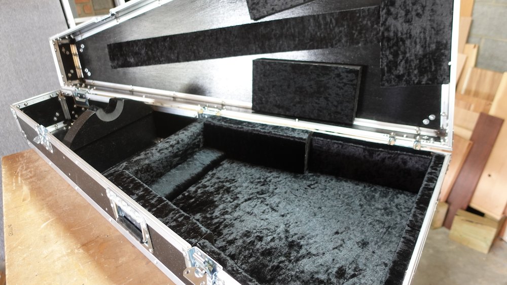
Completed case |
Completed case |
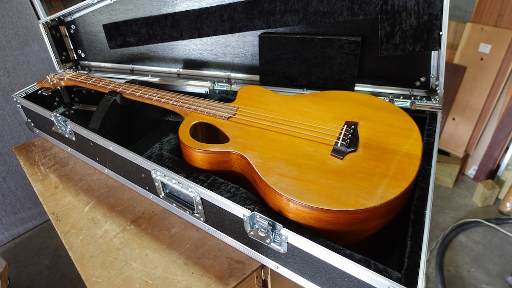
Completed case with occupant |

All content Copyright 20xx Trevor Magnusson
| × | |