Guitar Build Process
Quick links:
Milling bulk stock in advance
Access port cover and frame
Neck block & tongue assembly
Truss rod
Neck, headstock & heel
Headstock veneer
Continuing the neck
Sides
Finishing sides
Back and soundboard
Fitting back and soundboard to sides
Bindings
Fretboard
Fitting neck to body
Making bridge
French polishing soundboard
Complete all construction steps
Installing frets
French polish rest of guitar
Attach bridge
Setup
Pickups
Hardware information
Build history
Before beginning build
It's a pain when we have to hold up a build while waiting for missing stuff
check that all hardware is in stock or on order:
tuners, fretwire, saddle, nut, strap buttons, stringscheck that adequate timber is in stock:
neck pieces in particular should be well-rested in the workshop
Milling bulk stock in advance
Access Port
Tasmanian Oak, 2.5mm thickness
(Lengths to be steam-bent need to be 560mm, for simplicity's sake they can all be that)
Model |
Widths |
Bass |
25, 50, 98, 100, 106, 125 |
GP, Parlour |
25, 50, 71, 78, 100, 125 |
Universal (trim) |
25, 50, 78, 106, 125 |
Blackwood, 2mm thickness
Model |
Width |
Bass |
82 |
GP, Parlour |
54 |
Jarrah strips: 12x2mm
Neck Block
Tasmanian oak
(Lengths can be anything really)
19x90mm* |
mill to 8mm |
(backing plate) |
19mm stock |
rip to: 20, 28mm |
(U-channel) |
19x65mm |
rip to: 4mm |
(tongue/tenon) |
* 90mm stock allows for backing plate to be 65 (Guitars) or 67 (Bass & 12-string)
Fingerboard support extension and tray
Tasmanian oak
(Lengths can be anything really)
Fingerboard support tongue |
19mm stock |
mill to 16mm |
Fingerboard support tongue |
16mm stock |
mill to 3, 5, 10 |
Fingerboard support tray sides |
13mm stock |
mill to 5, 9, 10++, 16++mm |
Support tray bottom plate |
72-92mm stock |
mill to 5mm |
Support tray side bracing |
42 or 65mm stock |
mill to 5, 8mm |
(wider/thicker variants for Bass & 12-string)
Neck reinforcing spline
8 x 18mm (but best to wait until channel is routed)
Headstock Veneer
Celery-top Pine & dark*Blackwood: 110 x 2.4mm
Lengths: 210 (bass & 6-strings), 250 (12-strings)
Alternatively: dark Jarrah
* to allow for contrast with resin logo
Fingerboard
Spotted Gum, 66 x 6.5mm
Model |
Blank length |
Bass |
700 |
Guitars |
590 |
Fancy fingerboard binding (optional, and only for glued-in neck option)
Lengths same as fingerboard
Jarrah |
7 x 2.5mm |
Celery-top Pine |
7 x 0.7mm |
Understated fingerboard binding (optional, and suitable for bolt-on neck option)
Spotted Gum* |
7 x 3mm |
* ideally, from same piece as fingerboard
Sides, back, soundboard
Best left to when they're needed so they don't warp or cup over time
Bracing
Tasmanian oak
Lengths: depends on guitar model
8 x 16mm |
back, upper bout, vertical taper |
12 x 19mm |
back, lower bout, rounded over, to lie "flat" |
8 x 19mm |
soundboard, "A-frame", vertical taper |
8*17..19mm |
soundboard, "wing" braces |
8 x 5mm |
sides |
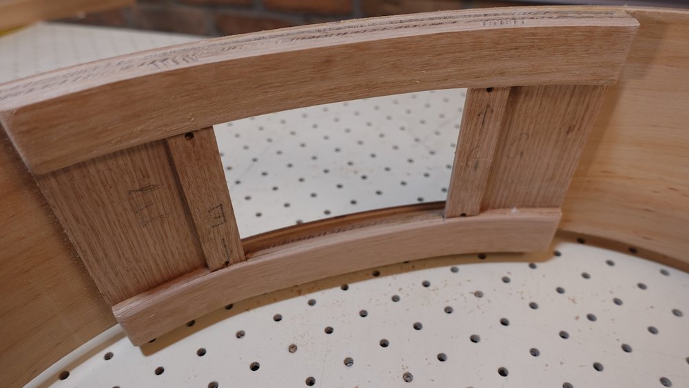
Kerfed lining
King Billy Pine
Radiata Pine (works ok, low rent)
Macrocarpa (a bit splitty)
19 x 7mm, rounded over on one corner
Lengths: 800-900mm
Bindings
950(bass) x 9 (850/800 for guitars)
NB: all pieces must be the same height, for effective tape-clamping force
Simplest plan, may need refining
Timber |
Thicknesses |
Pieces per build |
Celery-top Pine |
0.8 |
4 |
Jarrah |
0.8, 1.6, 2.2 |
4, 2, 2 |
Layout:
Side |
Layout |
Total thickness |
Soundboard |
J0.8, CP0.8, J1.6 |
3.2 |
Back |
CP0.8, J0.8, J2.2 |
3.8 (leaving room for tilt-bevels) |
Bridge blanks
Spotted Gum
10mm thickness
Bridge is approx 50x152, but larger for CNC router
Heel cap
Jarrah
10 x 60mm, length not important
Pickguard
Jarrah
70 x 2.5mm
Truss Rod Cover
Jarrah
55 x 3mm - though laminated is recommended
Access port cover and frame
Overview:
cut lengths
steam bend
assemble cover (door)
assemble frames (using door to get dimensions perfect)
drill holes and prepare nut strips
For the cover, there will be six layers, in three pairs
inner pair (smaller hole)
middle pair (larger hole)
outer pair (larger hole, outer layer Blackwood)
For the frame, there will initially be only four layers (two pairs)
This is because the outer layer will be the sides of the guitar
However, after the frame is fitted to the sides, two additional layers will be added
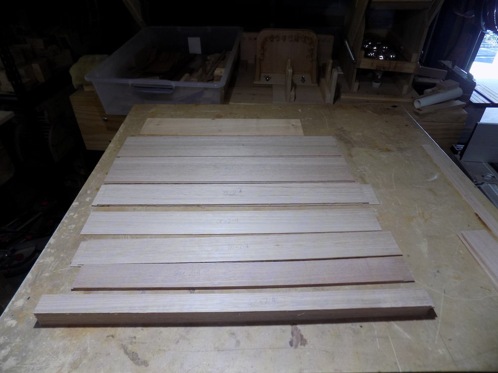
Resaw & mill tas oak stock into 2.5mm sheets
Do the same for a smaller amount of Blackwood for the outer, show layer
mill this to 2mm, and also a vertical-grain backing layer - to equal thickness of guitar sides
Note that the measurements below are workpiece end-targets, leave stock a little wider so that trimming to final size can be done later.
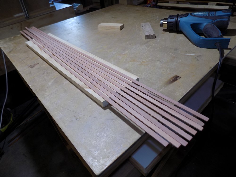
All pieces 2.5mm thick
The 25mm is a minimum, 30 is OK
Model |
Bent lengths (2.5mm) |
Straight lengths (2.5mm) |
Bass |
98mm, 106mm, 25mm |
100mm, 125mm, 50mm |
GP |
71mm, 78mm, 25mm |
100mm, 125mm, 50mm |
Parlour |
71mm, 78mm, 25mm |
100mm, 125mm, 50mm |
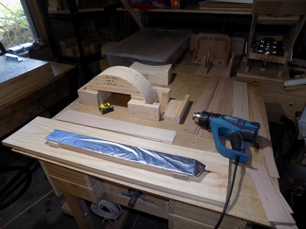
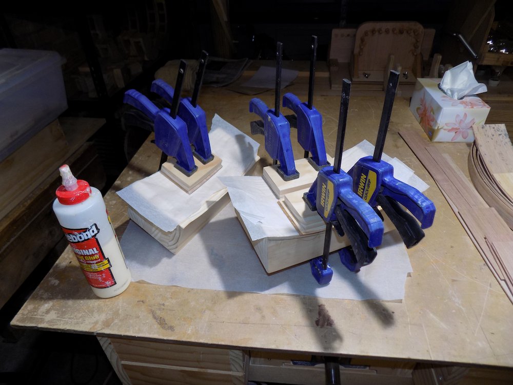
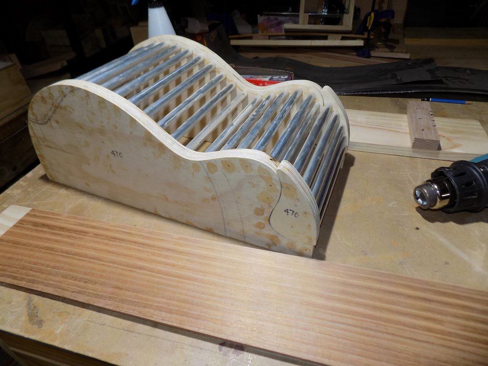
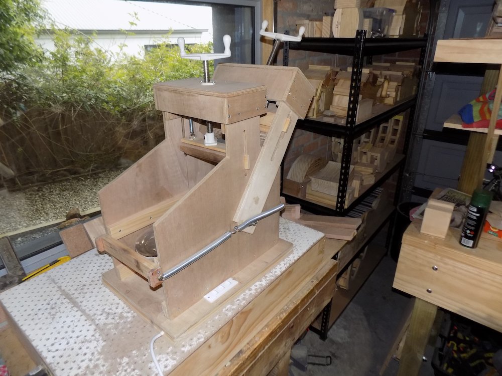
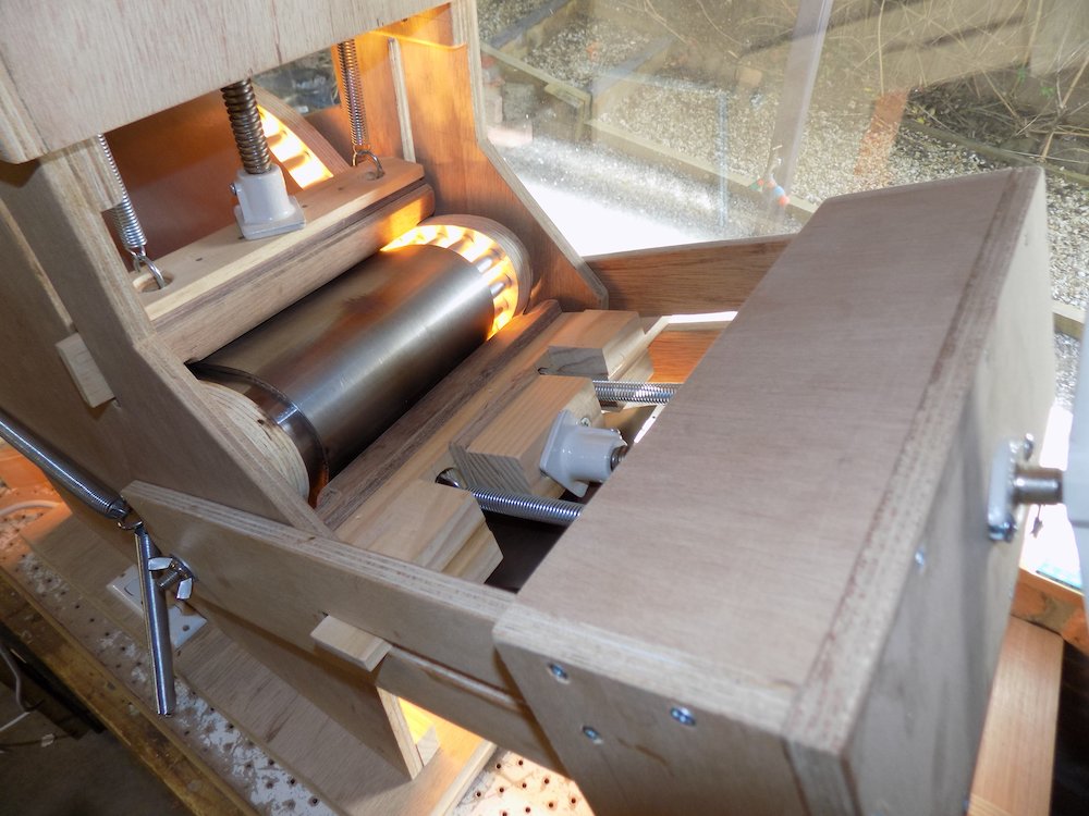
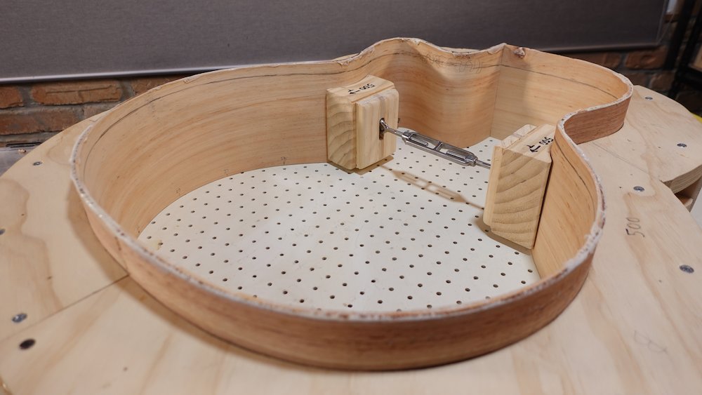
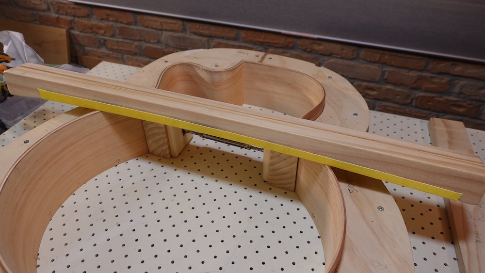
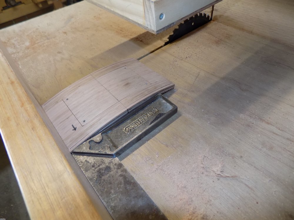
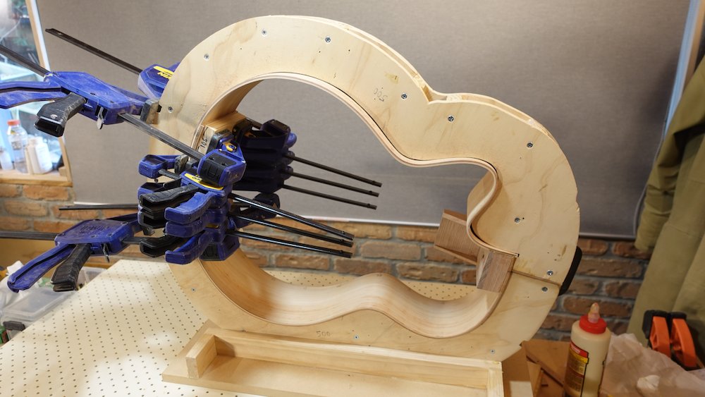
Cut bent stock into 560mm lengths & steam bend
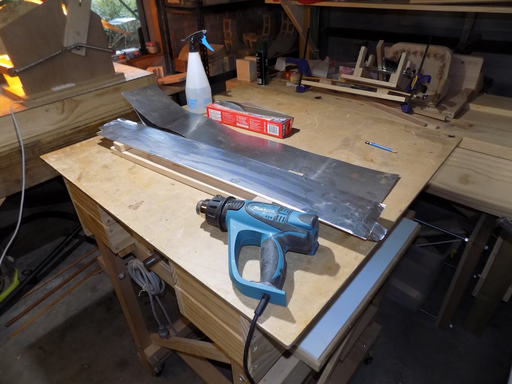
moisten strips, then layer two at a time (for 25++mm widths, two lots side by side)
wrap in aluminium foil
heat with heat gun
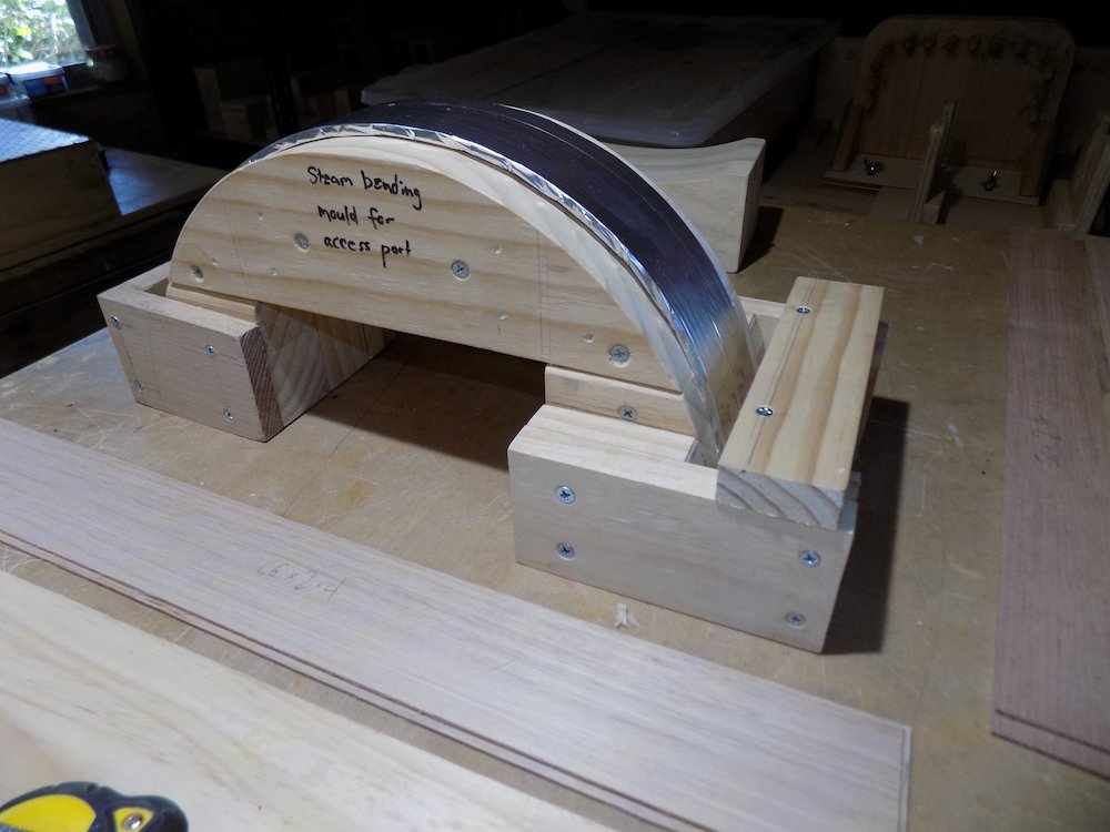
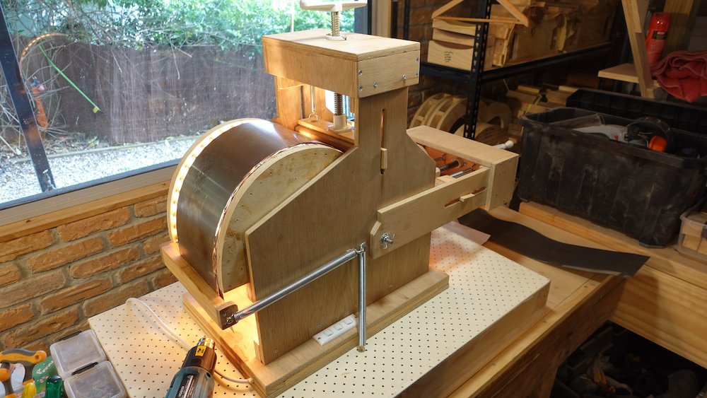
place in mould, clamp for about 5 mins total
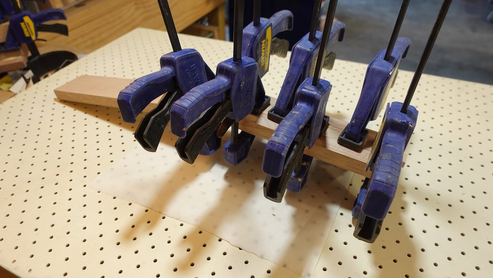
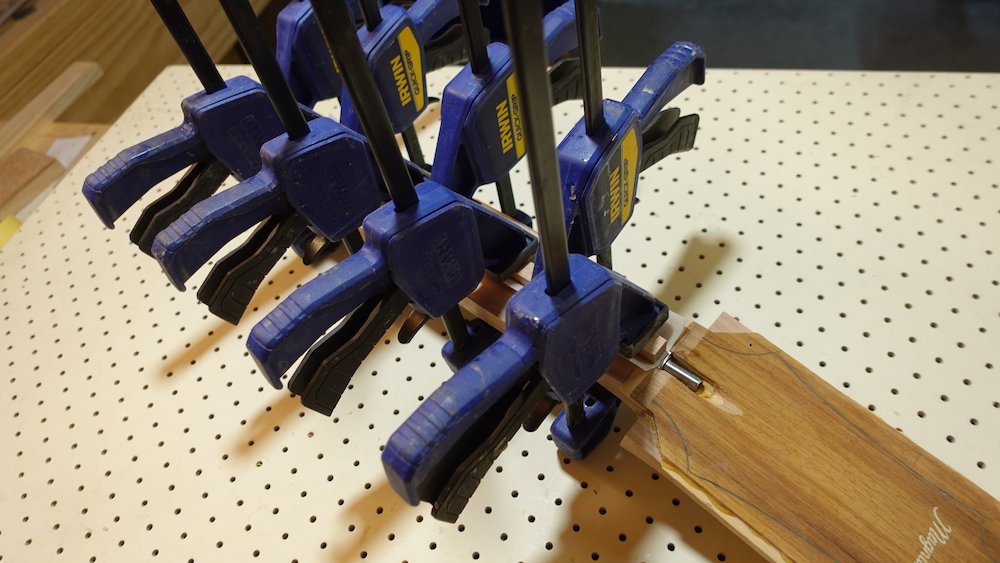
while still warm, swap ends over, re-clamp (try to even out any unevenness in curve)
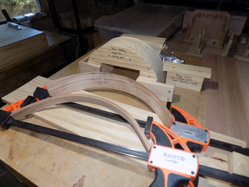
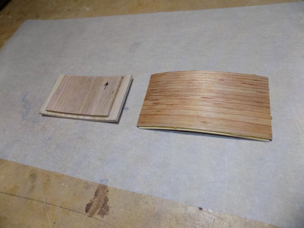
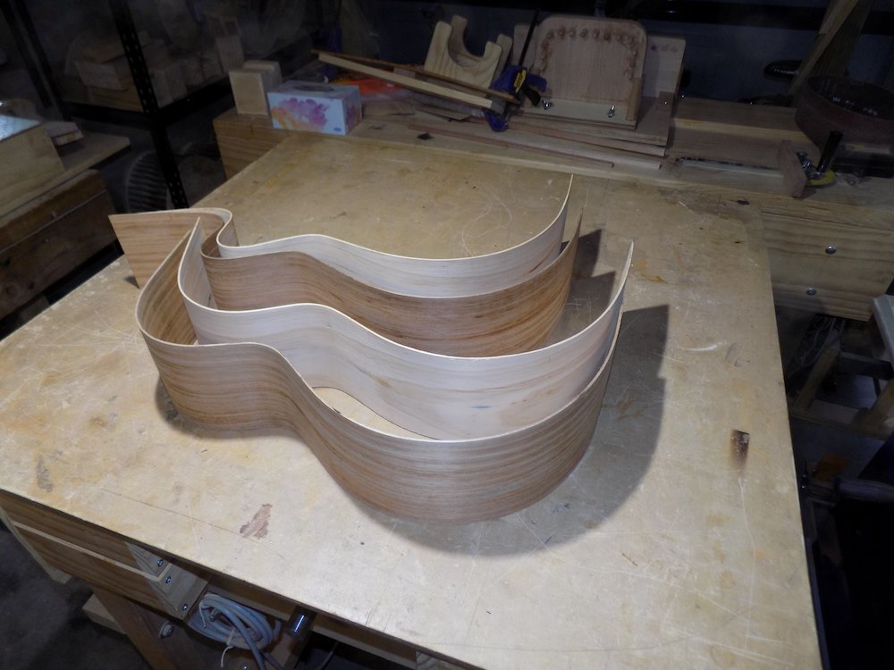
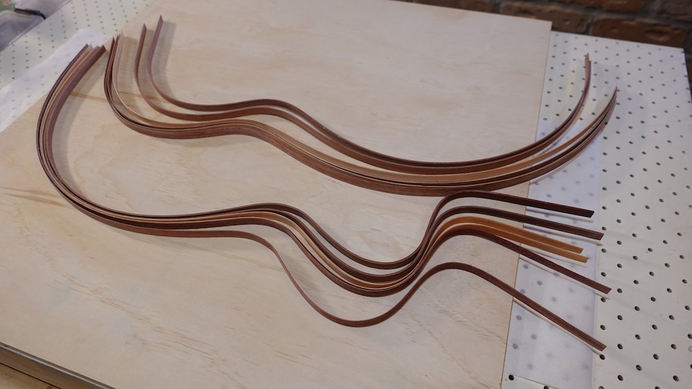
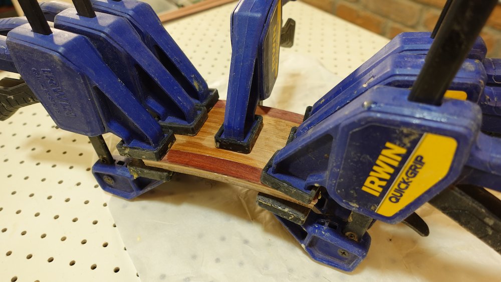
when cool, remove from mould, remove aluminium foil,
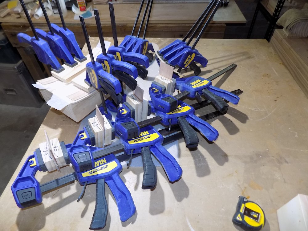
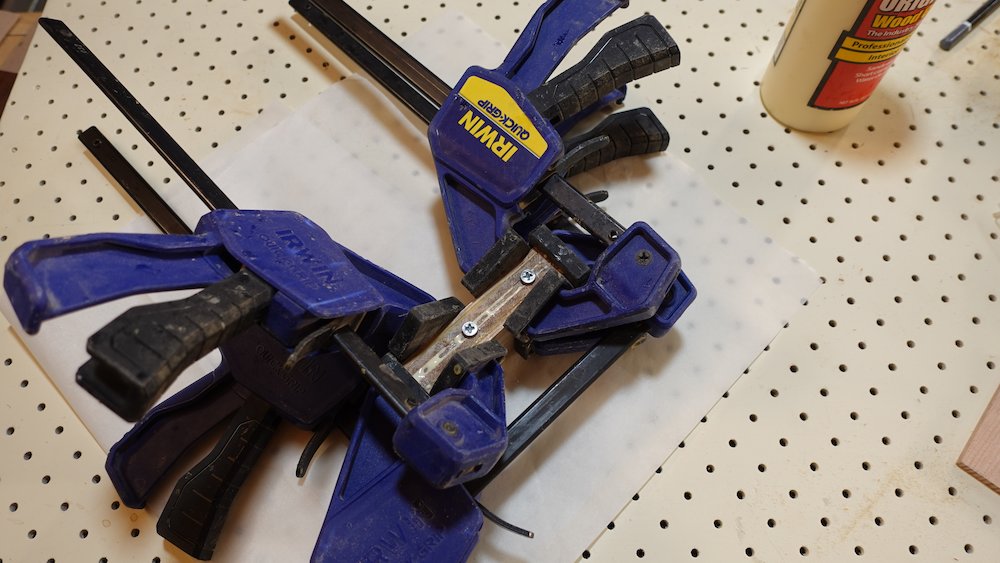
hold lengths in long clamps while drying
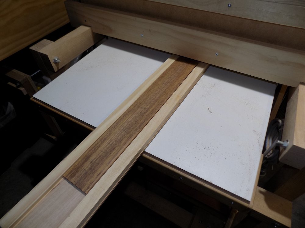
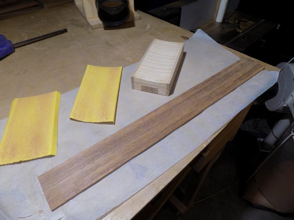
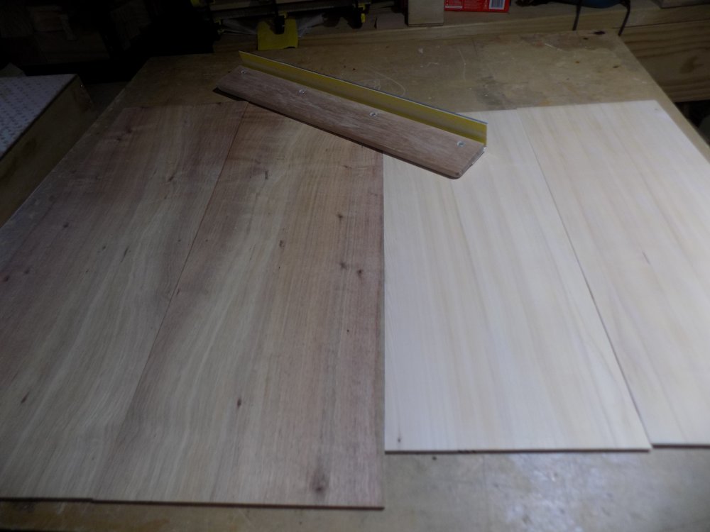
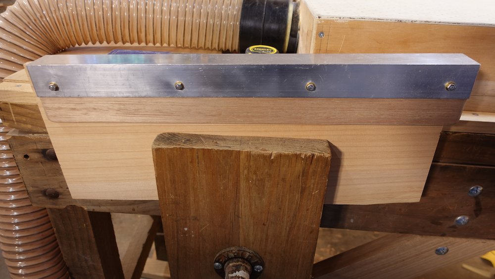
Milled stock |
Applying heat |
Bending in mould |
Drying bent pieces |
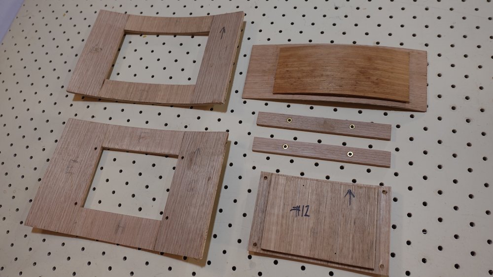
Covers
Model |
Inner layer |
Outer layers |
Bass |
100x98mm |
125x106mm |
GP |
100x71mm |
125x78mm |
Parlour |
100x71mm |
125x78mm |
Note that the outermost layer will actually be a little wider due to the "nested" nature of the lamination.
six layers, alternating grain, two "smaller", four "larger" (outer one Blackwood)
laminate in pairs, using bass mould and matching cauls for outer pairs, guitar mould for inner
for each pair, the outer layer of the curve has lengthwise grain from bent pieces, inner upright grain from flat.
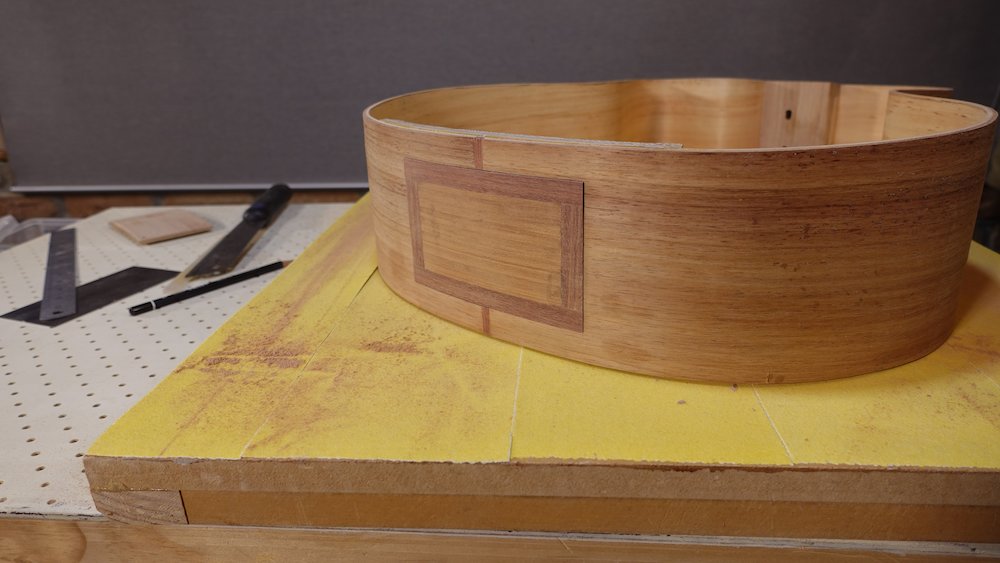
The outer "show" layer, from 2mm boards, is a little different
may well have both pieces lengthwise grain, as per guitar sides)
we usually have aJarrah border on the outermost layer,
in this case, we should wait until it is time to fit the outer layer into the guitar body
The border process is
wait until it is time to fit the outer layer into the guitar body
sand the the outer layer's inner ply to fit
cut the center piece from blackwood, leaving space for border around side
using centre piece to balance vertically, glue in centre piece, top and bottom
glue the side pillars
Trim to dimension/tidiness using belt sander
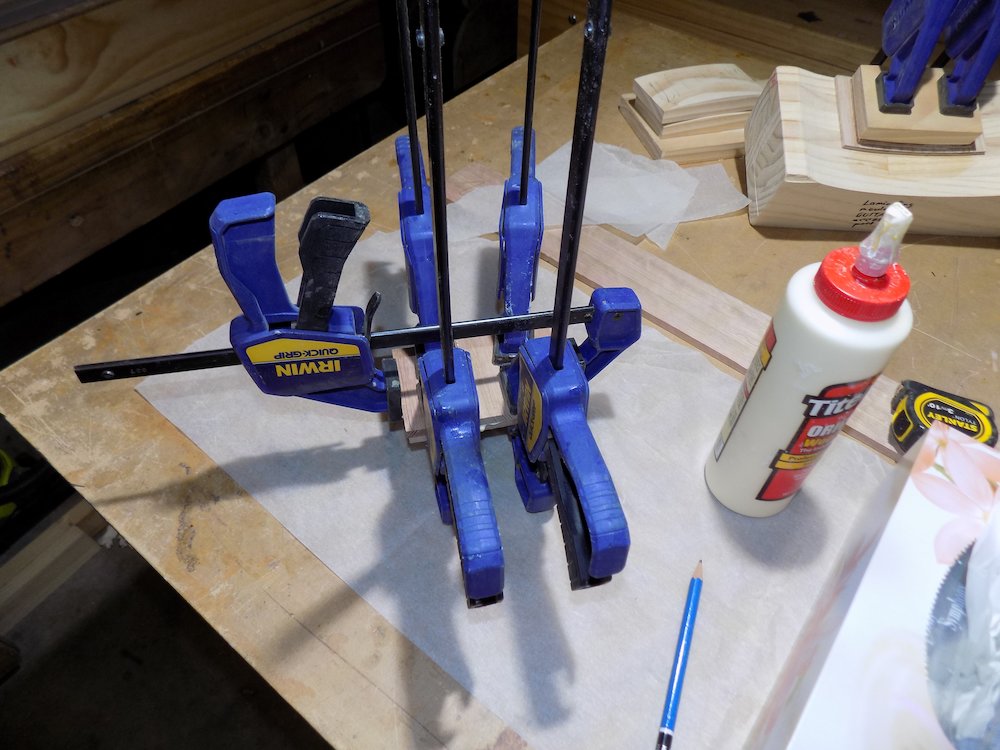
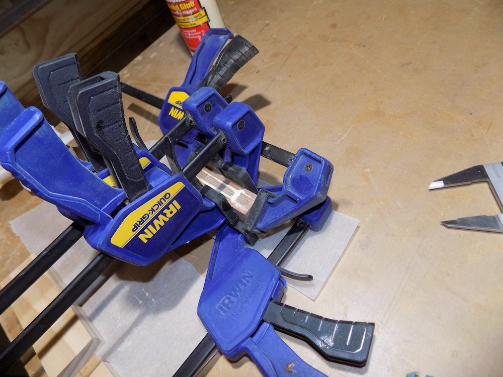
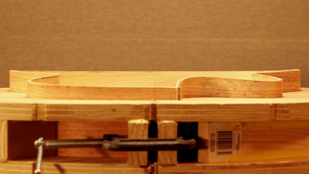
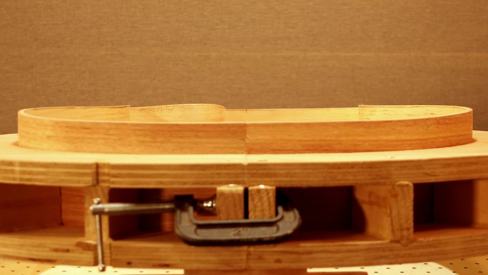
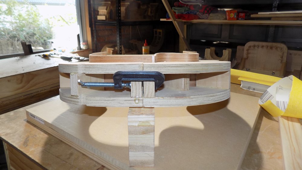
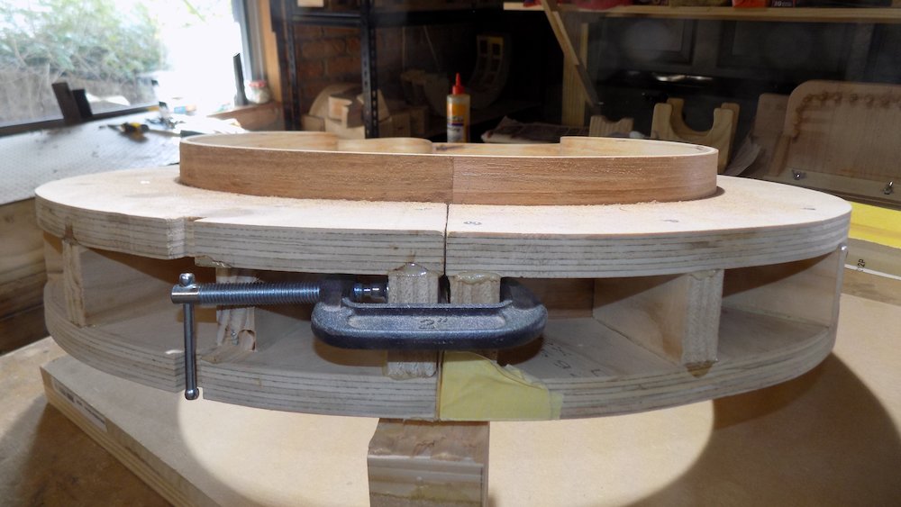
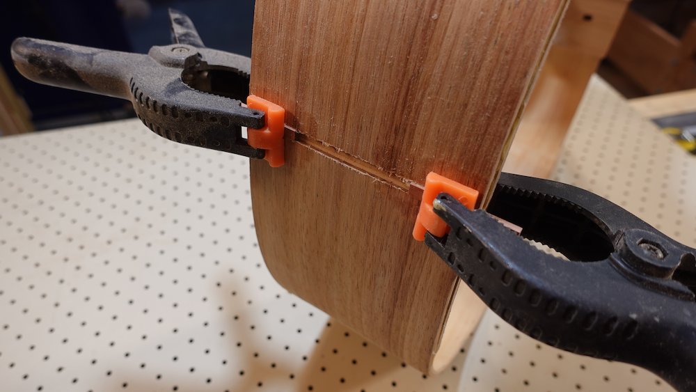
Then laminate two pairs - inner and middle - together:
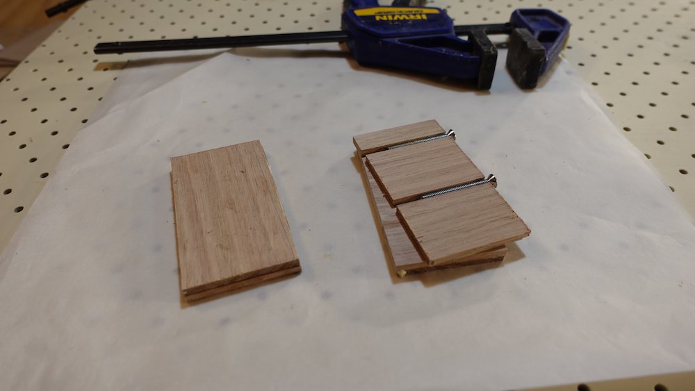
check curvature of laminating mould against solera mould, with any neck-join shimming in place
tack together with thin nails for alignment,
optional: place nails such that we can clamp around them
otherwise: glue and clamp without moulds, clean off squeeze out,
when confident, remove nails and clamp using moulds(Outer pair will be laminated later)
Laminating cover layers |
Cover pieces |
Frames
Dimensions:
frames should be constructed to extend 50mm each side, and 25-30mm top and bottom
frames will be trimmed later, final dimensions determined by guitar sides
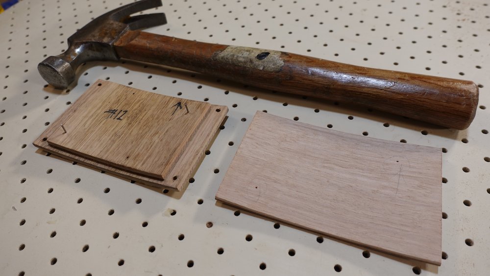
Cut all pieces, using laminated cover for measurements
Note that lengths on all curved pieces, and the heights on all straight/vertical pieces, can be rough
Since the two cover pieces were trimmed on the belt sander,
the widths of the vertical pieces will need to be adjusted.
label these pieces to match the corresponding cover edges.
Do all this before gluing (or there'll be some awkward chisel work)!
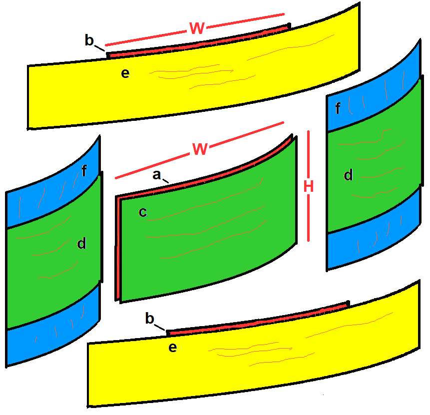
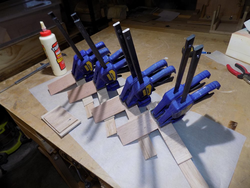
Laminate the individual pieces, as in access_port.docx diagram below
Notes
In every single case:
Vertical, straight pieces are "inside" the curve, in in the concave side
Top & bottom have "longer curved pieces"
Sides have "longer straight pieces"
Don't worry about squeeze out from the frame inner edges, that can easily be sanded.
However, do clean up squeeze out from the inner, "stepped" corners (where the shorter piece ends), as this area is a glue face in the next steps.
Acess port layers |
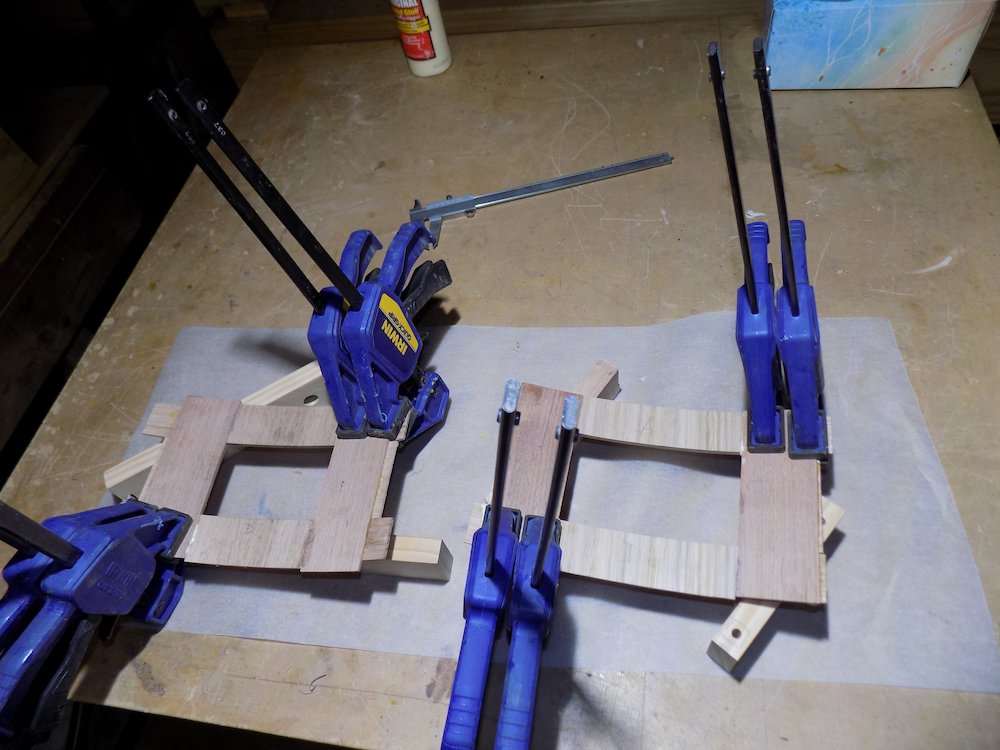
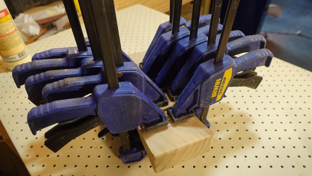
Clamping
Tops and bottoms: can be clamped "as is", as vertical-grain pieces are "thin". However, the access port moulds (and matching cauls) can be used if desired.
Sides: used pairs of small curved cauls, ideally *just* short of the curved-grain widths
Assemble each layer using cover as template,
Separate layers, sand all surfaces so that joins are "flat"
Hold assembled (with covers in place) and trim roughly
Do not glue frame layers together
Frame components |
Laminating frame veneers |
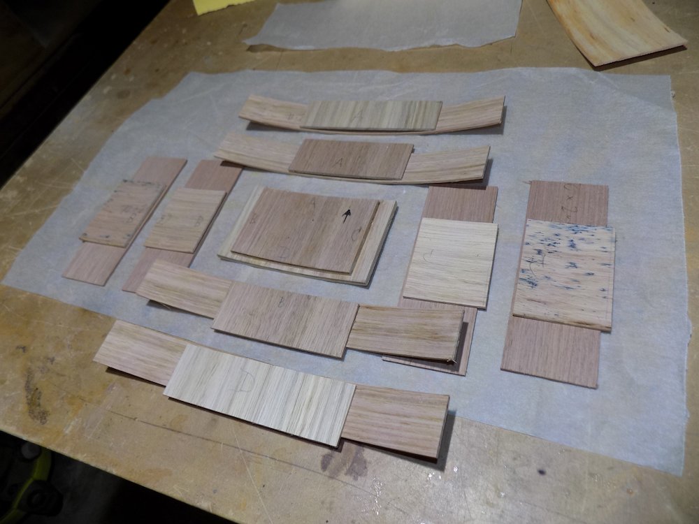
Joining frame pieces step 1 |
Joining frame pieces step 2 |
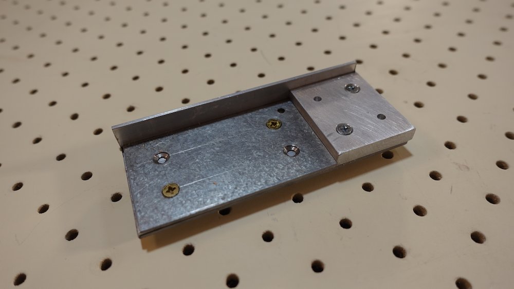
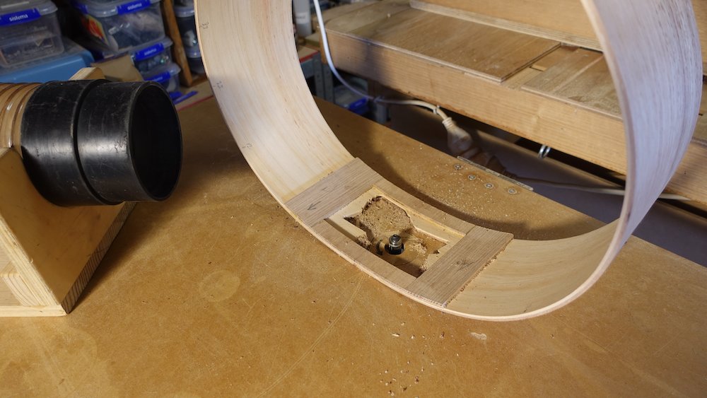
Drill holes in cover and frame
Use regular drill press, Dremel has some vibration issues
1/8" bolts - will use brass nuts and bolts
Using aluminium corner-hole guide, drill first in corners of port cover, from outside inwards
use a sharp drill bit
3mm holes, centres about 6mm in from edges
back with some 13mm scrap on drill platform to get curved surface horizontal
Then drill holes in back layer (of frame) using cover to guide drill (press all layers together)
back with a suitably-thick strip of scrap, to raise workpiece so it hole is level, and also provide clean exit hole
Cut two nut-strips of wood, 4x15
position so they overhang the opening by about 3-4mm
this will support the quite close-to-the-edge hole in the inner layer
Drill 3mm holes in the nut strips, matching those on each side of the port
Enlarge these holes to 5.5mm, but only halfway through (ie, 2mm), on the surface that will be glued to the inside of the frame
Hammer nuts into these holes, so that they are flush with the surface
These are to hold the nuts so they will neither twist, nor be pushed forwards when screwing in access port cover
Do not glue yet - final step requires sides to be completed
Corner hole guide |
All access port components |
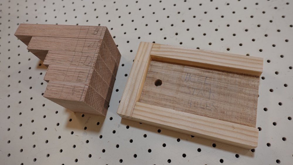
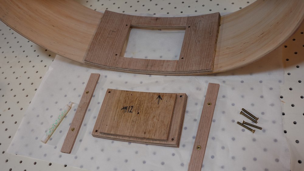
Neck block & tongue assembly
Overview:
laminate receiver back plate and tongue
glue the three "U" pieces to form the neck block mortise
drill aligned holes in neck block & tongue (20mm lower down for for bolt-on neck option)
* for bolt-on neck option
trim top of neck block by 13mm with one-degree angle (upwards to soundboard)
construct fingerboard support extension and support tray components
glue support tray to top of neck block
cut 5mm side brace channels and glue in side braces
In the following discussion
The term "receiver" refers to the neck block, specifically with respect to its engineered (rather than cut) mortise.
The term "neck tongue" refers to a piece that will eventually be glued into the heel, thereby becoming a tenon
Plan neck block width
Model |
Total |
Left upright |
Mortise |
Right upright |
Regular guitars: |
65mm |
19mm |
19mm |
27mm |
Bass & 12-string: |
67mm |
20mm |
19mm |
28mm |
It is therefore advisable to construct an oversize neck block, then trim it to size (and squareness)
Resaw and mill 19 x 90mm tas oak stock into 8mm stock
two boards can be got from one length
Cross-ply laminate to form receiver backing plate (will need two side-ply pieces butted together)
Bass: |
140++mm |
(neck end dimension 130, but there is an upward ramp) |
GP: |
110++mm |
(neck end dimension 99, ditto) |
Parlour: |
105++mm |
(neck end dimension 94, ditto) |
Note that these lengths are the original, non bolt-on neck design. For bolt-on neck, we'll be trimming them shorter.
Trim square when dry
Rip 19mm thickness stock into three pieces per guitar, will form the "receiver" of the neck tongue
NB: each of these measurements are after trimming - can make some of them larger and trim/cleanup
Component |
Bass |
GP |
Parlour |
Base |
65x20 |
65x20 |
65x20 |
Thin upright |
121x20 |
91x20 |
86x20 |
Thick upright |
121x28 |
91x28 |
86x28 |
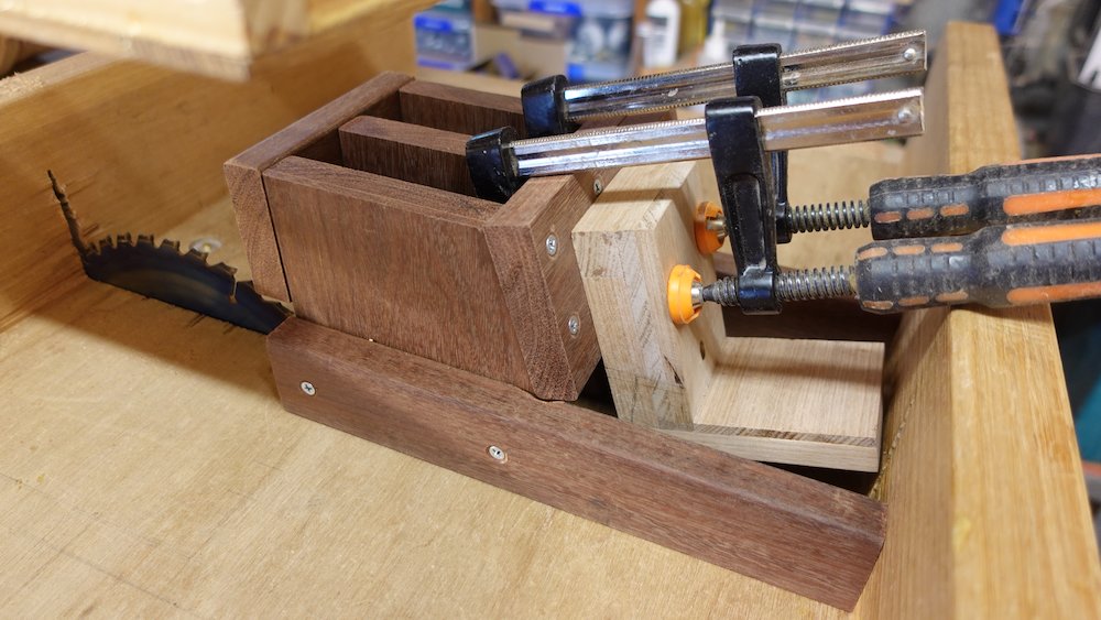
Glue to the cross-grained face of the laminate block,
in the shape of a "U", with the thick piece on the right.
Use the base & thin upright to ensure the channel is perfectly square to the laminated block
slower-but-better: glue it in three steps, bottom, thin, then thick
Use some 19mm waste as a spacer while gluing
Trim/clean up on table saw, round-over the show face (thick upright side) - but only if not bolt-on neck option
NB: after trimming, width should be 65/67mm, thin upright should be 19mm, as per table above.
Neck join tongues
Resaw & mill some 65mm width stock to 5mm and 9mm thickness boards (perhaps even 4 & 11mm)
Component |
Bass |
GP |
Parlour |
Tongue |
115x45 |
85x45 |
80x45 |
two outer layers, grain lengthwise (up & down), 5mm thick
one inner layer, grain sideways (ie inline with as neck), 9mm, will have to butt-join (don't bother with 75/80/110mm wide stock)
laminate, trim, thickness to 19mm using holding channel jig and drum sander if required (minor adjustments can be done using belt sander)
Laminating receiver back plate |
Laminating neck tongue |
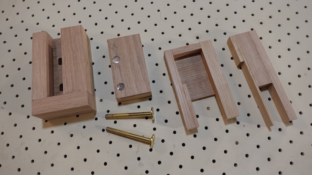
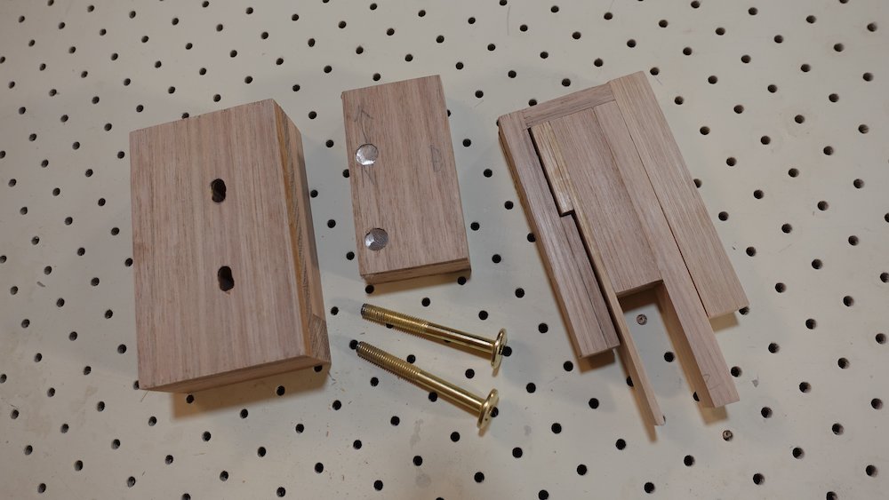
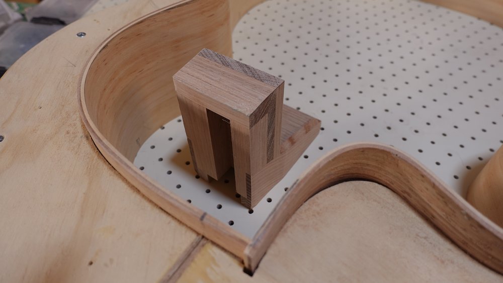
Alternate method for neck tongues to ensure perfectly aligned holes
Assume bolt-on neck option (top hole lower down for fretboard support extension tray and vertical bolt)
Use five layers of 4mm stock, the inner three transverse grain, outer two lengthwise
Innermost layer is split into three pieces, glued with 4mm bolts as spacers for holes
These voids act as pilot holes to guarantee perfectly aligned holes when drilling
Model |
Length |
Middle widths |
Bass |
115 |
13, 63, 32 |
GP |
85 |
13, 33, 32 |
Parlour |
80 |
13, 28, 32 |
Alternate neck tongue construction |
Laminating alternate neck tongue |
Check tongue fit into neck block
NB: Label each side of tongue top/bottom/neck/body
NB: leave some space at the bottom, for vertical adjustability
Choose nuts (need to be set into tongues)
also bolts (need to be 60mm long, and possibly trimmed later)
I chose M6 60mm Allen-headed bolts & matching 5mm deep nuts (or transverse barrel nuts)
That means the main holes need to be 6mm diameter
If not using "alternate" neck tongue construction
Use centering jig to drill two holes in backing plate
measure 15mm from each end of tongue
NB: for bolt-on neck option, top hole needs to be 35mm from top of tongue
with tongue centred vertically, mark positions in receiver channel (leave space above and below for adjustment)
a centering jig is a piece of 19mm stock with pilot hole dead centre
insert into receiver, drill holes through pilot hole into backing plate
fit tongue, use holes in backing plate to drill starter holes in tongue
remove tongue from block, finish holes in tongue,
using transverse-barrel nut squaring jig to keep the holes as straight as possible (ie, exit in the centre of the tongue)
For "alternate" neck tongue construction
enlarge holes in tongue, use those to drill holes in backing plate
Glued neck option
Bolts are for clamping neck to body, not intended to remain in work
Tidy slots are acceptable aesthetically, but could conceivably be plugged or covered
Bolt-on neck option
Bolts remain in work, allowing easier neck fitup, fretting, French polishing...
If using standard nuts: drill 10mm deep 10mm diam counter-holes in the exit (neck)
Force-fit two nuts into 10mm holes, so they are flush
Note: the inner nut is the only one that will apply tension, the outer is just to prevent it from being knocked forward
Clamp tongue to avoid splitting
Thread one bolt 25mm onto the nut
Use the bolt as a centering guide to hammer the nut into the 10mm hole
Once the nut is just beneath the surface, tap it out, thread the second nut just nestling, not locked, and hammer them both all the way in
Check that the bolts can engage with the nut from the other (body) side
If using furniture barrel nuts: use jig to drill transverse holes
Use stainless steel barrel nuts
They are typically too wide, and will need to be ground down
Use either a drill bit, or a M6 bolt to hold the tongue in the correct location
This means we can only drill 10mm starter holes (do one on each side)
To facilitate fitting the neck, there is one more step
vertically elongate the two holes in the neck block, 2mm top and bottom
very carefully use router table with fence attached
This will allow the tongue to slide up and down, and tightened at the correct height
Controlling the router to get tidy slots is tricky, options include
enlarge the holes using a drill first, so that the router can spin freely on startup
before locking the fence, spin the router backwards so that it nudges the work until there is no engagement
use a smaller router bit (but most smaller bits aren't long enough)
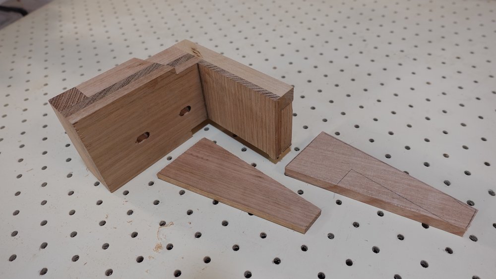
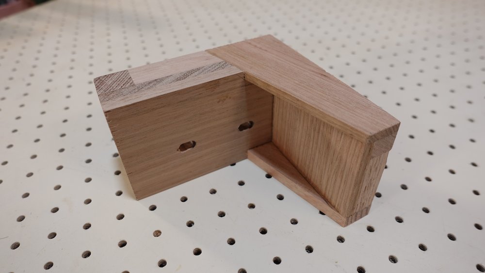
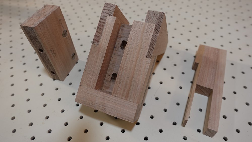
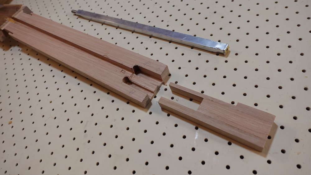
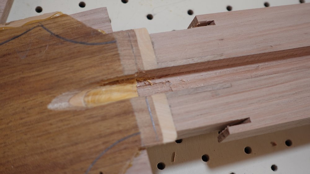
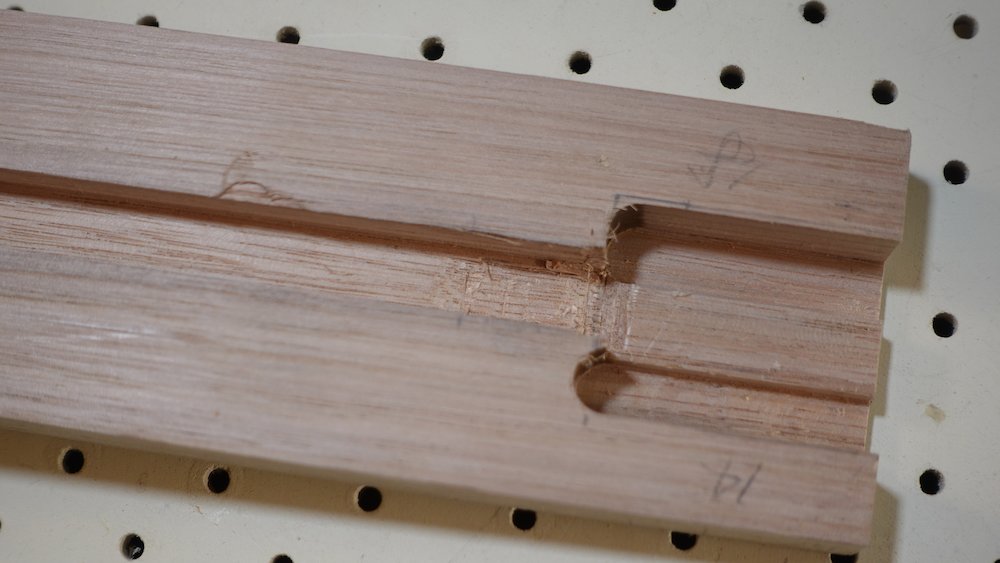
Neck block components |
Fingerboard support loosely nestled |
Bolt-on neck option
construct neck block and neck-tongue as per regualar glued neck, with two exceptions:
(a) the top bolt-hole needs to be 20mm lower (allowing for both tray and additional downwards-poking bolt through tray)
(b) don't do the round-over on the wide edgeprepare fingerboard-support extension and support tray components, as per diagram below
The 16mm thickness allows for some thinning down later while still having enough clearance for a flush-bearing router bit for soundboard
Cut off top 13mm of neck block, at a one degree angle (~0.7mm across the 32mm of neck block)
For a 110mm GP:
cut off 12mm (leaving 98mm)
raise bottom of piece by ~1.7mm to get one degree
cut bevel
For a 105mm Parlour:
pretty much the same
For a 140mm Bass:
raise bottom by 2.5mm
Prepare and glue fingerboard support extension and support frame pieces, 13 and 16mm deep,
Depth:
Support piece |
16mm |
Tray sides |
13mm |
Width:
Regular guitars |
65mm |
Bass & 12-string |
67mm |
This can be achieved by making the side pieces thicker, or the tray end-piece longer
Length:
leaving pocket 39x{extension}mm:
Parlour |
~60mm, based on 14th body fret, 21 frets |
GP |
~63mm, ditto |
Bass |
~80-90mm, depending on fret count / fretless equivalent |
Glue support tray sides to neck block
NB: at this stage:
both pieces should be at final width
the fit should be perfectly flush and square(Check that top neck-tongue bolts can still be fitted)
Confirm that everything is square and flush, for fitting the side bracing
Clamp work in side bracing channel jig, and cut away two triangular channels along each side
Cutaway side: 8mm
Non-cutaway side: 5mmTrace, cut and glue matching triangular (or rather, trapezoidal) pieces of 8 & 5mm stock
Proceed with build steps until it is time to fit neck
Fingerboard support pieces |

Side bracing channel jig |
Side bracing channels cut |
Side bracing glued in |
Bolt-on neck components |
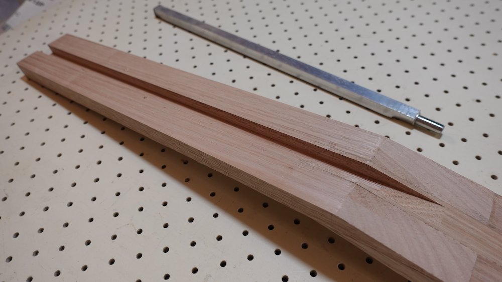
Truss rod (if not using a bought one)
Overview:
cut channel and threaded rod to length
assemble torque nut, tension nut, weld and grind
convert hex head barrel nut to truss rod nut
grind U-tops of aluminium channel down to 10mm (leaving 17mm untouched at each end)
assemble with spacer nut in middle of channel, fold flaps at each end around tension nut & threaded rod
NB: Regular acoustic guitar truss rod is too long for my GP model
there is not enough room for neck-tongue slot!!!
Therefore, can only use bought truss rods for bass
(as nothing available in parlor size)
Make Martin-style truss rods as per this video
https://www.youtube.com/watch?v=ysKRHdIaaEg
with some changes
use a furniture bolt "socket" nut instead of T-nut
12*12mm channel
M6 threads
3/16" / M5 washers (small diameter, they fit M6 threaded rod)
truss rod nut make by grinding flange of hex socket barrel nut
Lengths
take body-fret position (eg 345.1 for 24.5" scale, 14th body fret)
-25mm (neck-body clearance, also space for neck tongue channel)
-2mm (socket nut flange)
-0.5mm (washer)
This is the aluminium channel length (318 in the above case)
Cut/grind coupler/barrel bolt to 15mm
Threaded rod should be this length +8mm (will be trimmed later) (326 in the above case)
Scale length |
Body fret |
Aluminium Channel |
Threaded rod |
24.75" |
13 |
304 |
312 |
24.75" |
14 |
321 |
329 |
25.5" |
13 |
314 |
322 |
25.5" |
14 |
332 |
340 |
34" |
14 |
451 |
459 |
Method
cut threaded rod & aluminium channel to length
grind a 12x12mm square nut so that it friction fits in the middle of the U-channel, so tensioned threaded rod pushes against it for more bowing
fit regular M6 nut - the torque nut
fit furniture socket nut - the end nut
tighten them against each other
grind the sides of the torque nut square, with three facets flush with the furniture nut shaft
the rod, nut torque nut and end nut shaft should fit snug into the aluminium channel
weld the torque nut to the rod, then re-grind so it's square again
temporarily insert a long bolt into a hex socket barrel nut
grind off the flange, then put temporary bolt into hand drill, and hold it against grinder while spinning, to form a cylinder shape.
Finally use drill press as a "lathe" with sandpaper to polish it.
grind off the tops of the threads above the inserted square nut if required, so nothing extends past top of U-channel
U-channel
cut 3mm slots 17mm from each end (into the "top" of the U)
scribe a line 10mm from the U-bottom (2mm to be removed)
grind/cut/file/sand between the notches, so the U is 10mm high (notches now mark "flaps")
insert threaded rod one end
bend over the flaps at each end (vice)
grind off the portions of end-nut flange that protrude, leaving a squared end
NB: important
the threaded rod is only approxomately the length we need
if it is left too long, the truss rod adjustment nut will bottom out
remember (and check) that our adjustment nut has about 8mm of usable thread
thread a dummy nut, cut rod to exact size, remove nut so thread is useable
washer, wax/oil
spray with water dispersant
assemble & test
when adequately oiled, seal open side of channel with masking tape, and trim so channel sides are not covered
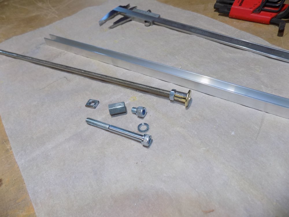
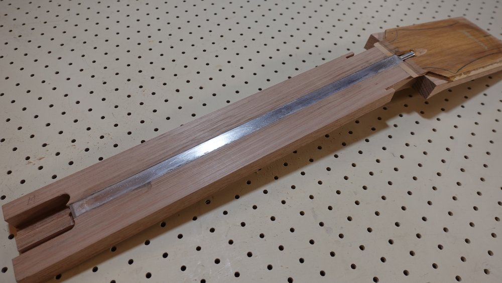
Truss rod components |
Truss rod preparation |

Truss rod weld |
Truss rod ready for assembly |
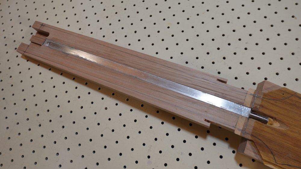
Truss rod nut construction |
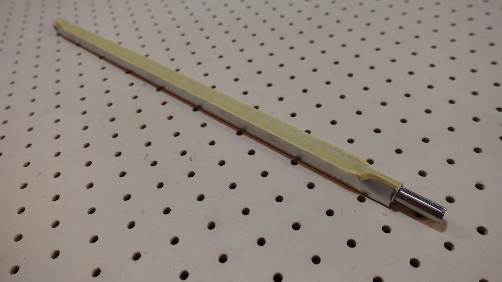
Finished truss rod (not yet sealed with masking tape) |
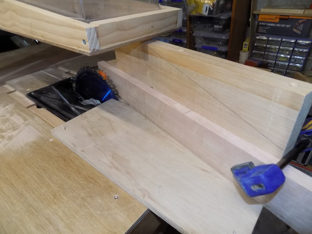
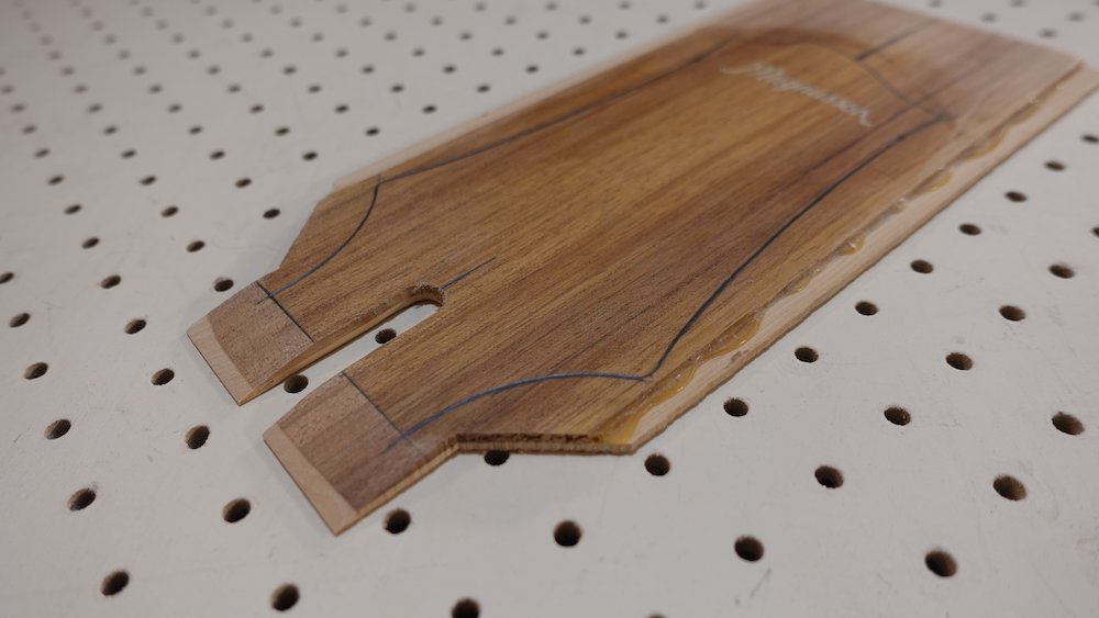
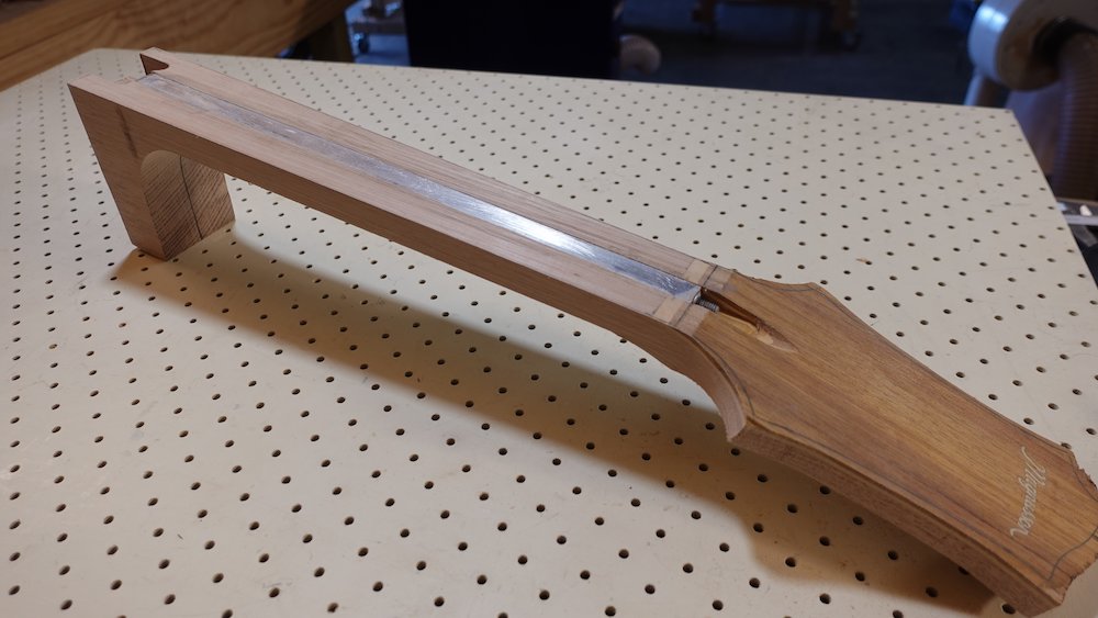
Neck, headstock & heel
Overview:
mark up a single piece of 19x65mm stock into pieces for neck, headstock, heel stack, and headstock wings
cut all square cuts
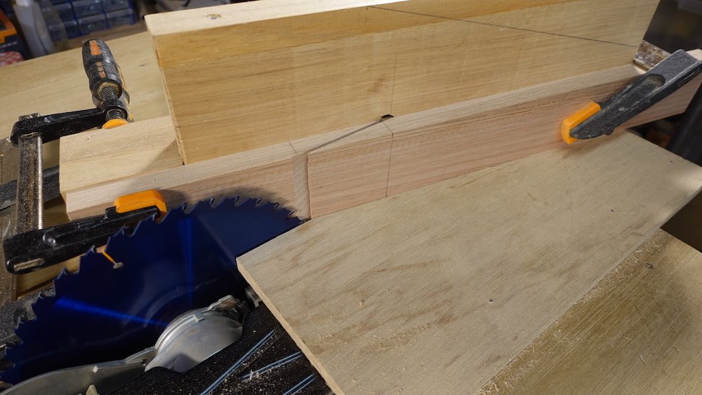
cut 14 degree scarf joint using jig
mill neck piece to a slight taper using neck-taper wedge, 16mm at scarf joint end, thickening to about 18mm at heel
level headstock angle across both pieces (neck piece on top, as we've messed with the angle)
glue scarf joint to attach headstock to neck
glue heel stack together
cut headstock spline channel, glue in spline and level
cut truss rod channel
rip headstock narrower, then attach wings to make it wider
thin down headstock, forming initial volute profile
optional: turn around "kiss" scarf joint from other side (use neck-taper wedge!)
Cutting necks to ~14deg angle
Rise |
19 |
Run |
75 |
Angle |
0.248 |
Slope |
14.2 |
Hypotenuse |
77.4 |
The table below takes into account...
kerf losses (in combination with 14-degree angle)
headstock veneer
headstock section initially thicker to leave enough "meat" for the volute
Stock width: 65mm
Scarf joint table
"Scarf cut start" measured from heel-end, scarf cut will end approx 75mm further towards nut/headstock.
Scale length |
Body fret |
Stock length |
(12-string) |
Scarf cut start |
24.75" |
13 |
556 |
596 |
336 |
24.75" |
14 |
573 |
613 |
353 |
25.5" |
12 |
548 |
588 |
328 |
25.5" |
13 |
566 |
606 |
346 |
25.5" |
14 |
583 |
623 |
363 |
34" |
13 |
680 |
460 |
|
34" |
14 |
703 |
483 |
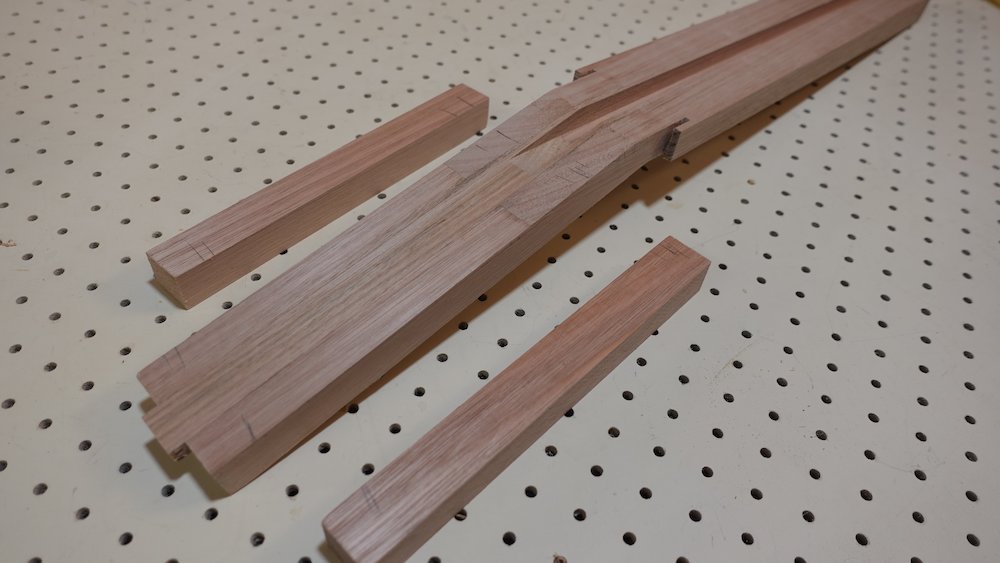
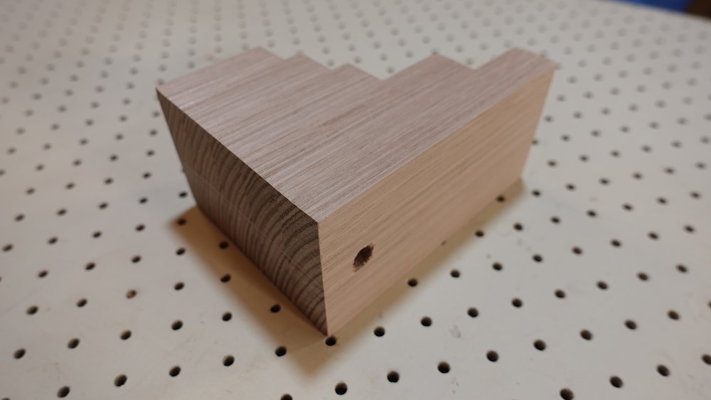
Heel pieces
Cut from same piece as neck, and adjacent to body-end of neck stock
Bass: |
130 at neck |
6 pieces (7*19=133) |
GP: |
99 at neck |
5 pieces (6*19=114*) |
Parlour: |
94 at neck |
4 pieces (5*19=95) |
Rough lengths: 125, 95, 65, 55, 50, 45
Cut heel and neck/headstock pieces, labelling each piece so that stacking the heel pieces can be done with exposed end-grain aligning nicely
Use well-rested quarter-sawn 65*19
Label so that any bow is *upward*, we don't want any back-bow baked into the neck
(fretboard will tend to produce more backbow, and we want to let the truss rod take care of it).
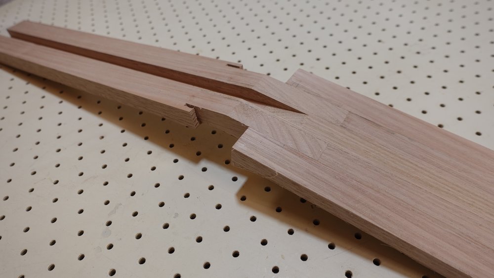
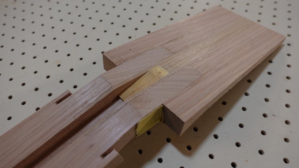
Cut scarf joint using jig on table saw
Aim for kerf to be evenly spaced around scribed hypotenuse line
Clean up wedge-ends by stacking so that hypotenuses align and sanding
NB: do this before drum-sanding the neck piece.
Get rid of any uneven saw grooves, blade-burn, and make sure each wedge-edge is straight and square
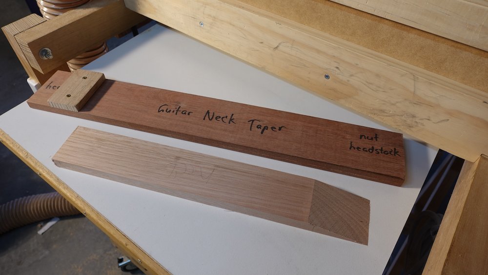
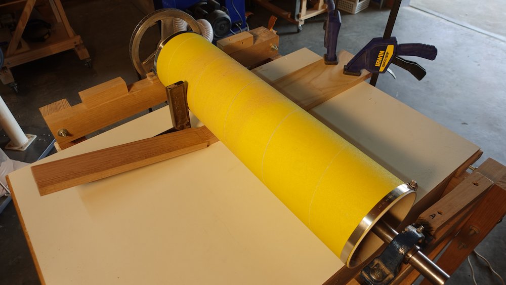
Mill neck stock down to a tapered thickness
Using neck-taper wedge underneath, make sure the thin end is where we want it thick, and vice-versa
Aim for 16mm at the headstock/nut end, and 18(ish) at the heel end
Do not do this to the headstock piece, we need it to be thicker, so that it can "slide down the fretboard" by about 12mm, to give "meat" for volute
Mill the "shallow wedge angle" side, not the sharp one (which would shorten the piece)
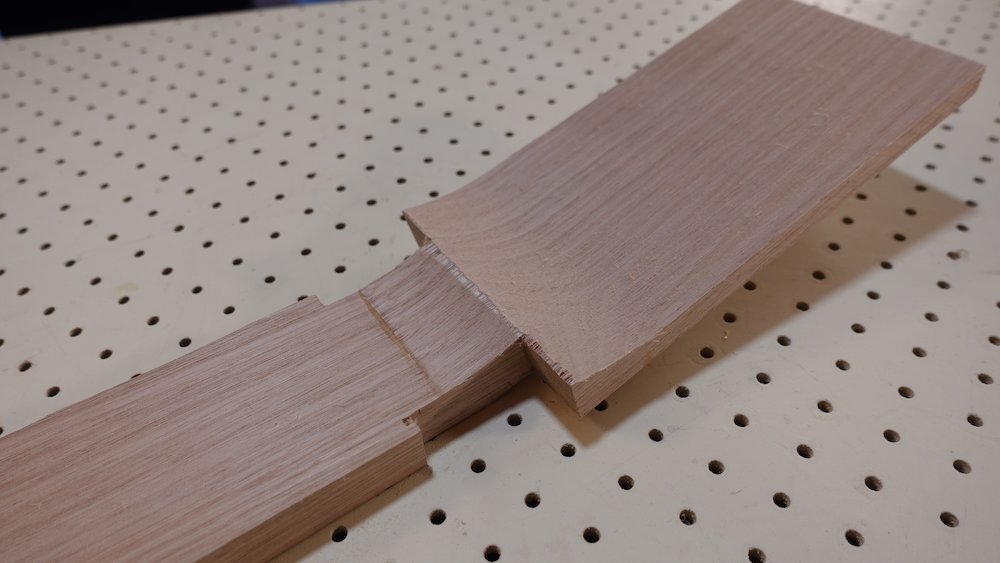
Finesse the two scarf joint faces with sanding block
Clamp both pieces together (neck piece on top) and level so all faces are perfectly co-planar
Sand so the combined plane is perfectly smooth, and all borders of the sloped faces are square
Scarf joint jig |
After cutting scarf joint |
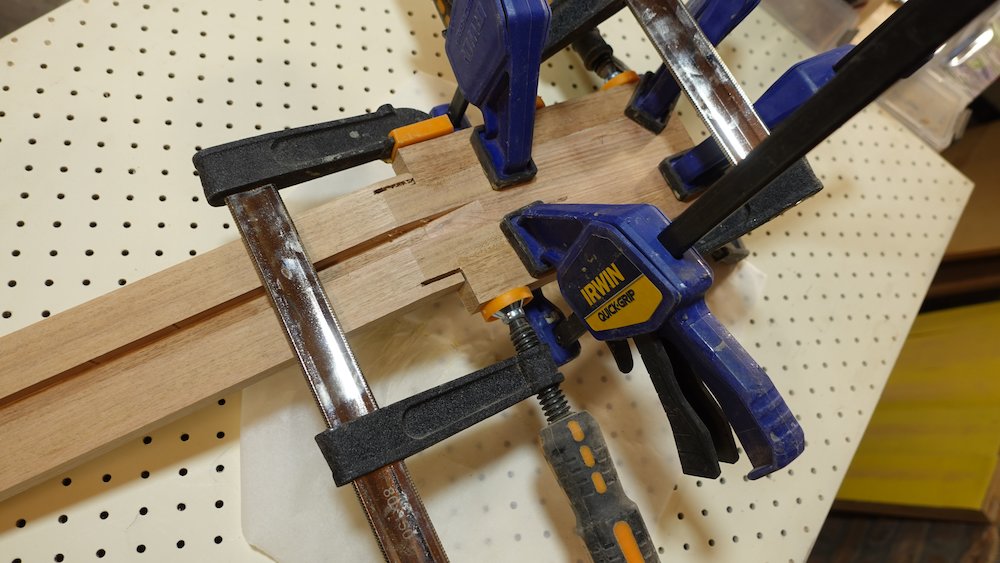
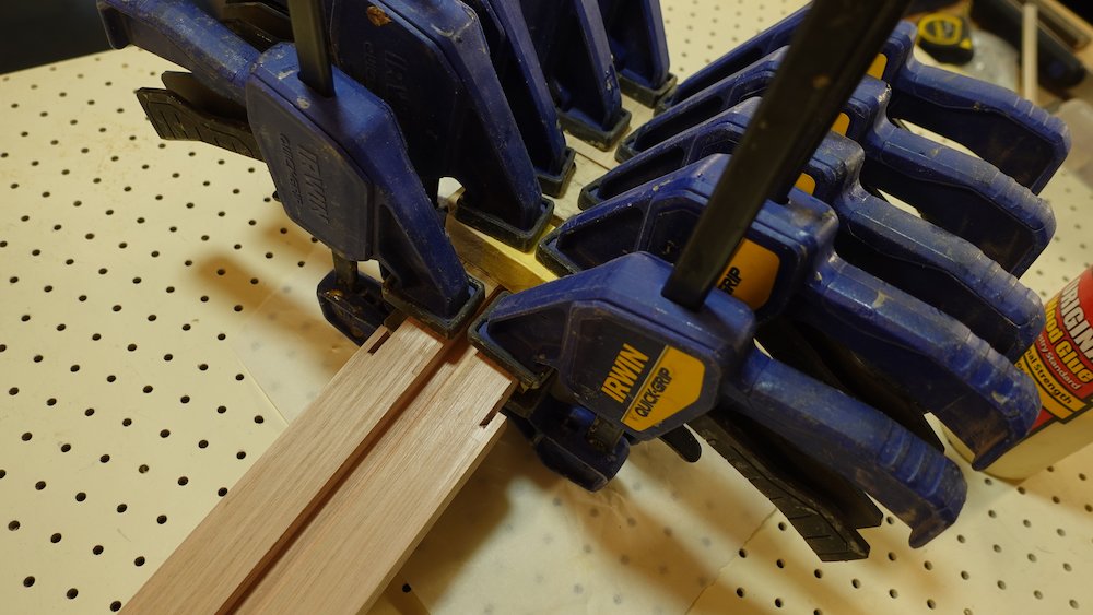
Align scarf joint using scarf joint clamping jig
This will solve two problems
It stops the two wedge pieces from being pushed apart when clamped
If keeps the neck and headstock piece co-linear, ie prevents rotation
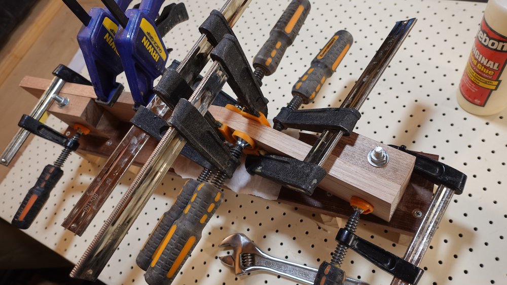
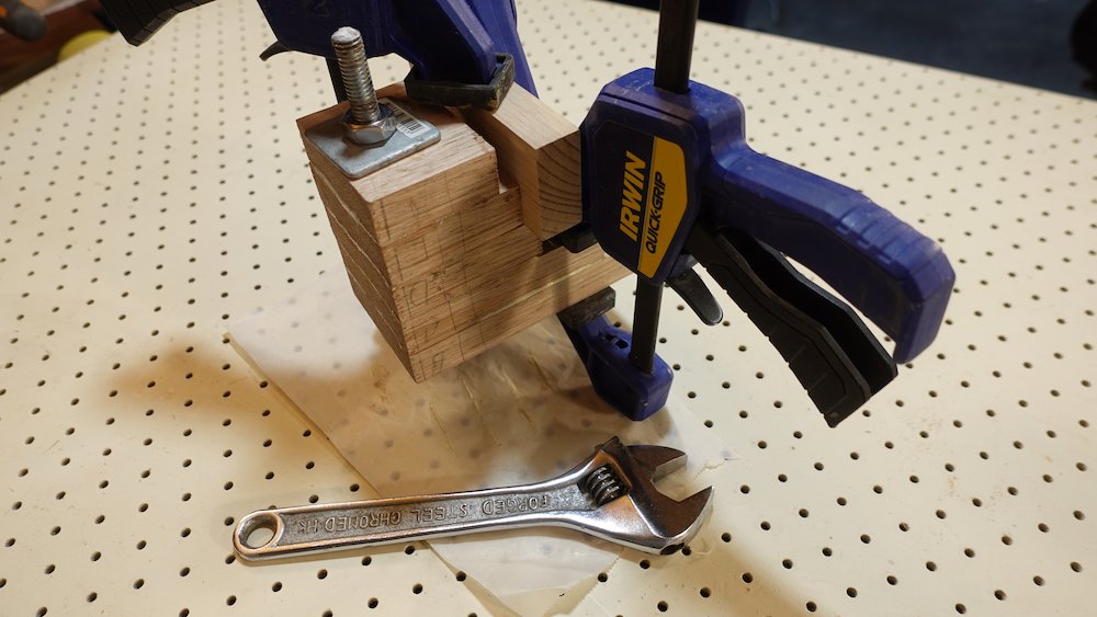
Glue up & clamp
Neck depth taper jig |
Cleaning scarf joint faces |
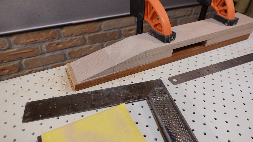
Scarf joint clamping jig |
Gluing scarf joint with jig |

If headstock piece is not perfectly aligned with neck piece
(This was more a problem before using the clamping jig)
After gluing, mark a true centreline along the headstock, taking account of any rotation if the headstock piece was not perfectly aligned with the neck piece.
Use masking tape to shim sides of the headstock (or trim using table saw), so that they are parallel to this line
This is necessary as the headstock sides run along the router fence when cutting reinforcing spline channel.
Any headstock non-alignment may also affect cutting the truss rod channel.
Use the heel alignment hole jig to drill 9.5mm holes in the heel pieces, then use a bolt when gluing them up
It will help the pieces stay aligned, and not slide when clamped
It will also assist with clamping (although additional clamps are still required)
Glue up heel pieces, making sure the grain lines up, but don't attach heel to neck yet
Clean up the upper face and sides of the headstock, perfectly flat, straight & square
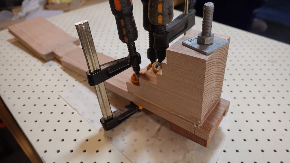
Heel stack hole jig |
Gluing heel stack |
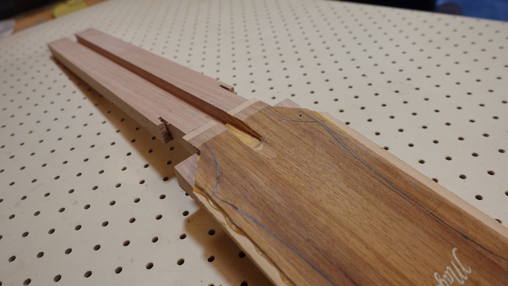
Reinforcing spline
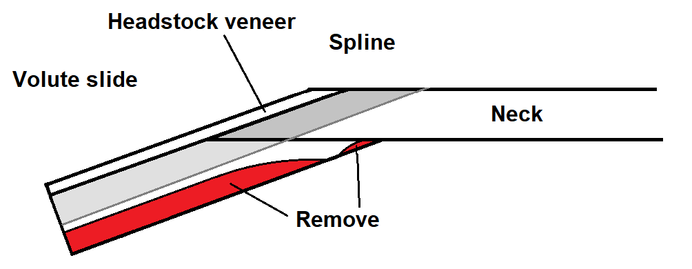
Cut a channel along headstock, 8mm deep, about 18mm wide,
"bevelling off" into the neck (see diagram below)
use router table
channel should be aligned with neck (if any rotation in scarf joint)
always feed the piece right-to-left to avoid router pulling it away from fence
Mill and glue in spline, then level with sander, sandpaper etc.
Scarf joint/volute diagram |
Cut truss rod channel (12mm wide, 10mm deep) using router table
NB: do this before attaching headstock wings!
Headstock wings
NB: cut truss rod channel first!
Before attaching headstock wings
Rip headstock piece to 52mm wide (balanced around centre)
This will place the two heastock wing join lines "inside" the headstock, avoiding them appearing along the headstock sides
It does however mean we have to do a bit of extra re-jointering...
Rip some 19mm stock, cut to headstock length-20mm:
6-String,Bass |
185mm |
12-String |
220mm |
Don't make them any wider than they need to be, thinner = more flex = more forgiving of imperfectly-jointered surfaces.
(Trim width to about 20mm or less)
Rough-up the outer (dressed) sides (or clean up the ripped faces), and glue to headstock,
starting around 20mm from top neck-headstock vertex.
Gluing reinforcing spline |
Truss rod channel cut |
Headstock trimmed |
Attaching headstock wings |
Trim headstock ends square - NB: square to NECK, if scarf joint rotated a bit!
Thinning headstock, also forming volute curve
Remove dust shroud from drum sander
Slide headstock under sander drum, find end-position to leave volute "end" curve
make a mark on the neck, 18mm from the inside scarf joint line (don't press too hard, pencil lines can dig into the neck)
using a square, position this mark under the "start" of the drum
On the sander outlet end, clamp a stop piece at the position of the (squared) headstock end
Jack up drum sander dust shroud with ~32mm offcuts (clamp them for security)
Thickness headstock to <11-12mm (depending on the headstock veneer), pushing the headstock under the drum, against the stop piece, then out again
there will be a tendency for the drum to stop before the workpiece hits the end-stop
this is because the drum will nestle into the circular profile it is creating
from time to time, check that the piece is really hitting the end-stop
aim for about 28mm of unsanded headstock underside
Turn the neck around, move the stop piece, and give the lightest dressing to the underside,
just "kissing" the scarf joint
This should result in a volute apex with the following characteristics
7mm in height, 2-5mm in length of unsanded headstock underside
after accounting for bevelled headstock veneer and nut thickness, apex should sit at the zero-fret position
Setting up to thin down headstock |
Headstock top after thinning |
Underneath showing start of volute |
Heel stack glued and squared up |
Headstock veneer
Overview:
laminate veneer blank
markup blank with centreline, tuner holes, headstock outline
prep blank with shellac
engrave logo
seal with CA
fill logo channels with resin and mica powder
level after resin hardens
roughly cut headstock outline, with extra extension at fretboard end
cut slot in veneer for truss rod access
partially sand in bevel at nut-fretboard end of veneer
glue an infill strip into the truss rod channel so truss rod nut access looks tidier
glue veneer to headstock
Resaw & mill Blackwood and Celery-top Pine to <2.5mm, laminate
Show layer is Blackwood, the pine is to provide a contrast stripe around the outside
Aligning the pine layer cross-ply may strengthen the headstock wing joints, however it also causes three issues:
it may render the piece curved, causing problems when thinning in the drum sander
when sanding the wedge, the bulk of the work must be done after gluing it to the headstock, as the lower layer has edge-aligned grain
when trimming the sides of thinning the neck, pull out is an issue as part of the top of the neck has sideways grain
therefore, if doing it, it is essential to have longitudinal grain at the neck-end
one solution would be to have a piecewise transverse section in the middle (where it won't be seen), with longitudinal grain all around the outside
Recommendation: don't do it
If the result has some curvature, moisten, heat and clamp to remove it - this can cause uneven thinning in the drum sander
Previous method: using a handmade 3:1 reduction pantograph and Dremel router
clamp pantograph to upper right corner of router table
use wrapped stylus, so no play in template channels
clamp work-holder jig "underneath" that, perfectly square
clamp template 200mm from bottom left, with piece of 19mm stock for stylus "rest spot"
template should be pretty square to table
see image below
put mill bit in Dremel as far in as it goes
make sure the chuck is tight!!!
make sure workpiece has headstock outline, logo position and most importantly, centre line marked
draw cross-line 40mm under the top wave-motif line - that will be base of "M"
soft-clamp the workpiece in the work-holder jig
hover stylus above M-middle-bottom, move workpiece so mill bit is on crossline-centerline intersection
make sure *centerline* of workpiece is square to holder jig (and therefore, table top), screw down wingnut clamps
rout the inlay, "hovering" the stylus at first, then all the way in
make sure to go back-and-forth on all three M-feet.
Setting up pantograph |
Routing headstock logo |
Resin for simple logos (without very fine lines)
Mix some clear glass sparkle, turquoise glass sparkle and fine green glitter in a mini bowl
Fill the routed channels with glitter mix, to just under the top
- should be able to scrape an edger over without dislodging any
Apply a few drops of low-viscosity CA glue to partially fix the glitter in place
Mix a capful each of epoxy resin and hardener in a plastic cup (or cut off plastic bottle, whatever)
Drizzle the resin in careful not to drag the glitter around (CA glue should reduce this risk)
- make sure it covers each edge
Butane flame or heat gun to de-bubble
heat gun underneath to encourage resin to ooze down into channel
more butane flame to get rid of additional bubbles
Logo channel filled with glitter |
Logo channel filled with resin |
Logo sanded level |
Finished old logo |
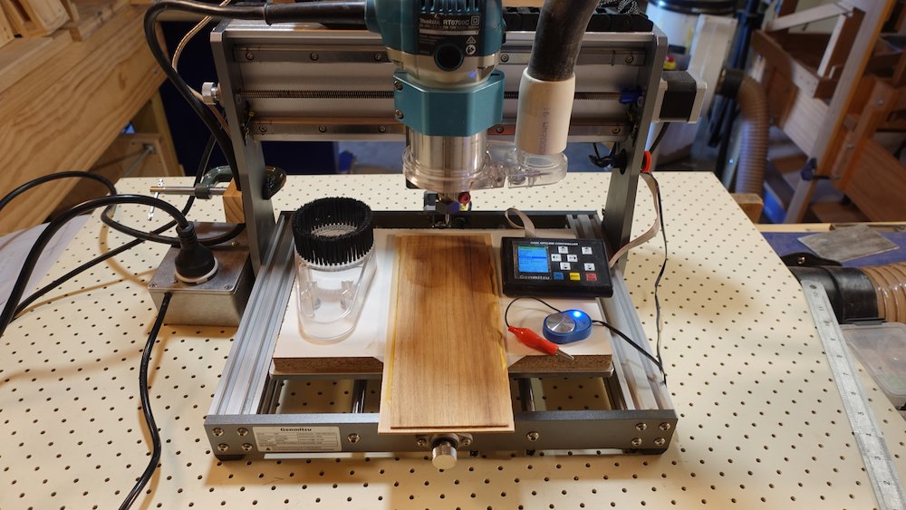
Current method: using a CNC router to engrave a logo with fine lines
My own custom "Magnusson" logo
30 degree V-bit
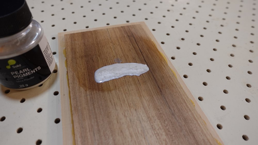
Stabilise grain by soaking some waxed shellac, diluted with alcohol, then wipe off and allow to harden
Lightly draw the centreline along the veneer stock (this line needs to bisect the middle "n" of the logo)
Trace the outline of the headstock from the wooden template
Transfer a line running through the two top tuner holes onto the veneer
Check that this line is perpendicular to the centre line
From the intersection of these two lines, find the point 20.3mm up the centre line
This point is the origin of the logo G-code, carefully position the bit to it and choose "Center XY".
After carving, lightly drizzle some CA glue into the channels to seal them. Do not allow it to pool anywhere
Mix some clear epoxy resin (one capful of each component), with two "scoops" of Opal White mica powder
(a "scoop" is from a 10mm piece of bindings strip)Drizzle the resin into the channels, de-bubble with a heat gun or blow torch
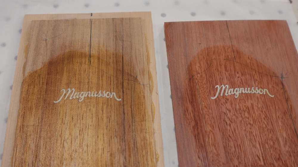
Allow resin to set until very hard - two days depending on weather
Sand down to wood - be very careful if using drum sander
Setting up CNC router |
Raw logo after CNC engraving |
Resin and pearl pigment applied |
Sanded back, also shown in Jarrah |
Mark up the headstock logo and cut veneer-neck transition line
Before any drum sanding, transfer the two end-points of the centreline to the sides of the piece
(so that we can recover it after it has been sanded out)
Carefully drum sand the veneer, first to reveal clean filled channels
then (front & back) to get down to 4mm.
If drum sanding pulled out any pieces of glitter/resin
fill with CA glue (may require more than one application) then level with fine sandpaper
NB: do this now, and keep doing it until the surface is perfectly smooth. French Polishing is not the time to discover this was not done adequately!
Reestablish the centreline, using the two "saved" end-points, above)
For the "M" logo, the line should go down the middle of the centre pillar of the "M"
For the CNC logo, it should go down the middle of the middle "n"
Retrace the headstock shape (onto the veneer) from the template, aligning with the centreline
Important: find the centreline at the far end of the headstock
Beware: if scarf joint is not perfectly square, more care is needed to find correct centreline
Transfer line so it is the same front and back
NB: in the following steps, 16mm is assumed to be the run of a 14-degree wedge of 4mm thick veneer
if the veneer is thicker or thinner, adjust to match
Trace two more lines onto the headstock veneer:
transverse line for the back of the nut,
and a parallel line 16mm forward (towards neck/body) of that
cut along this line
Mark a line on the headstock 16mm back from the scarf joint - this will be the back of the nut.
Cut truss rod nut channel and begin transition bevel
Plan for truss rod adjustment nut to extend 14mm further past the headstock end of the nut
The aim is for the end of the truss rod to be underneath the thickest part of the volute
Drill a 6mm hole in the veneer 20mm past the headstock end of the nut (4mm past planned end of truss rod nut)
Cut a slot up to the hole on the bandsaw
This slot will be wider, but we will finish it with a rat-tail file
The hole is just a guide
With the bandsaw, trim away some of the veneer waste around the nut-to-wings flare
With the belt sander, cut off about 80% of the "upward sloping" edge of the veneer,
making a bevel, coplanar with the top of the neck.
Glue infill into portion of truss rod channel along headstock
Mark zero-fret line on neck
Mill a 5mm strip of softwood infill for the "sloping" portion of truss rod channel
It will be about 40mm long
Taper it down to about 1mm height towards the zero-fret line
Glue it in, and bevel the portion that stick "out", level with the headstock face
This will improve the appearance of the truss rod nut slot
Truss rod slot and start of transition bevel |
Truss rod nut channel infill glued in (previous attempt) |
Glue veneer to headstock
Glue veneer to headstock aligning previously drawn centrelines
use two small nails (outside headstock perimeter) to prevent slippage while clamping
use cauls to even out pressure since the veneer is thin
Finish veneer bevel with sandpaper and/or scraper, making a perfectly flat and flush transition to neck
Finish truss rod adjustment nut slot with rat-tail file, to allow hex key access
The slot will parallel with the neck, bevel "up and out" of the headstock
Now is a good time to check for any neck-bow - remove by sanding and/or clamping
Gluing headstock veneer |
Neck with headstock veneer attached |
Continuing the neck
Overview:
widen truss rod channel at heel to accept bolt-on neck support prongs
deepen truss rod channel at each so truss rod fits flush
glue in truss rod with epoxy
mark up neck with zero-fret line, body-fret-line, tapered side edges
glue heel stack
mark heel curve, tapered neck edge lines and headstock outline (front and back)
cut and sand heel curve, neck edge lines, headstock outline and body-fret face
shape neck by drawing factet lines then cutting them with Shinto etc
If pursuing bolt-on neck experiment
Mark body-fret line on neck
Mark neck-end of truss rod (notes immediately below)
Using router, widen & deepen truss rod channel at heel end to accept fingerboard support extension "prongs"
16mm deep, as wide (and asymmetrically placed) as the support piece itself
Neck will be 18mm thick at the heel end, leaving 3mm at bottom of neck piece
Don't bother squaring them off, fitting the fingerboard support extension needs to be done later
Position truss rod so the end of the adjustment hex-nut extends 14mm past the back of the nut
Note that this corresponds to the aluminium section lines up with the fingerboard, and ends at the start of the nut.
We want the truss rod adjustment hex barrel to "just" protude up through the headstock veneer,
while the end of the truss needs to be above the extra thickness provided by the volute
The truss rod will have two deeper sections at each end (where the flaps are folded)
Use a chisel to carefully deepen the corresponding sections of the channel
Extra slots for fingerboard support extension |
Deepened channel at nut end |
Deepened channel at body end |
Truss rod sealed with masking tape |
If not done yet, put some masking tape over the open channel of the truss rod, trim sides flush
Mix some Araldite, spread some on the sides only of the truss rod channels
glue truss rod in place, if slightly low in the channel that's ok (not high)
Gluing the truss rod |
Truss rod attached |
If the truss rod is low in the channel
Rip 12mm lengths of very thin timber, glue over truss rod
This is most important in the middle, where it will push up against the fingerboard when tensioned
Scrape/sand everything flush
Using the headstock template, clearly mark & square the position of the *back* of the nut
If all has gone well, this should be *just* inside the newly-sanded/exposed neck-headstock break
Mark a (squared) line 6mm down-neck from this - this is the zero-fret line.
Now we can mark the body fret line
25.5"/14th-fret |
359 |
24.75"/14th-fret |
348.6 |
24.5"/14th-fret |
345.1 |
24"/12th-fret |
305 |
34"/14th-fret(bass) |
479 |
Now we can plan neck width profile
Mark centreline at body-fret, then *centred* body-fret neck width
6-string: |
56 at 14th fret |
12-string: |
59 at 12th fret |
Bass: |
58 at 14th fret |
Mark *centred* nut neck width
6-string: |
44 |
12-string: |
48 |
Bass: |
42 |
Rule in neck edge cut-lines
trace in headstock-neck transition lines (make them symmetric)
Take already-glued-together heel block stacks
If drawing a line on the underside of the neck, don't press too hard, pencil can dig in
Bottom of stack will be ~45mm
Bottom of heel will be 35mm
Position heel stack with about 5mm spare each end
Enlarge drilled hole through heel stack to ++10mm
Drill 10mm hole in neck to match existing holes in heel stack
Glue up, using bolt and clamps
Marked up neck |
Gluing the heel stack to neck |
Transfer neck edge cut lines (width lines) to the underside of neck
NB: heel block may not be square - use set-square
Transfer headstock outline to back of headstock:
Cannot cut headstock shape right way up due to headstock angle
This will be hard to get 100% accurate, when we cut it out (later) we'll leave plenty of space so that it can be finished on the belt sander with frequent checking of the front.
Use this diagram to rough-in heel curve.
Roughing in heel curve |
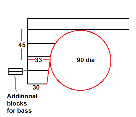
This is a very rough guide
Measure 45mm down from the underside of the neck piece
Measure 33mm in from the bodyline heel cut
Measure 30mm in from the bottom of the heel
Trace a quarter circle from that point to the underside of the neck piece
Extend the bottom part of the curve to 30mm in from the bottom of the heel
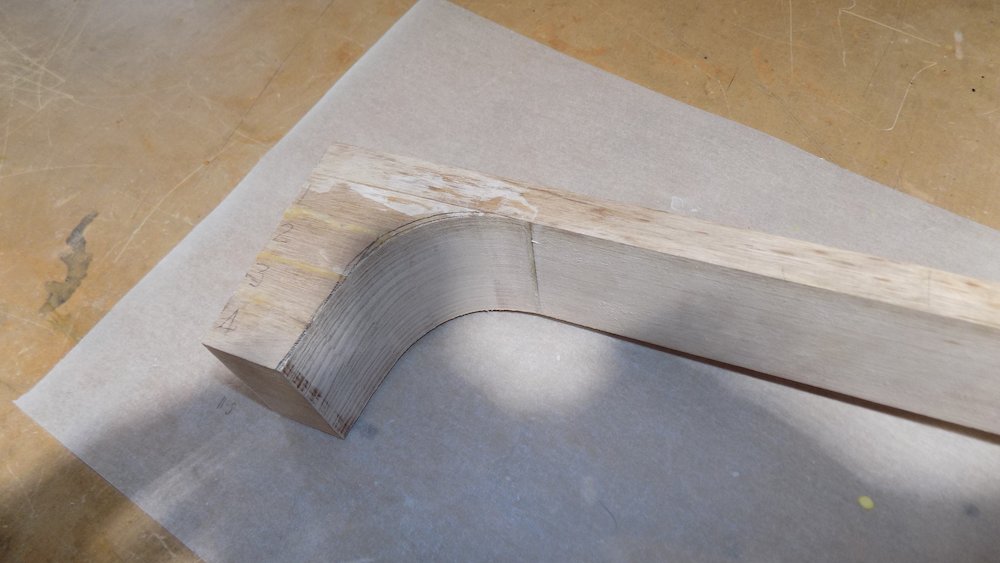
Rough the shape in on the bandsaw, then get closer on the belt sander
Cut the body-join line on the bandsaw using the mitre
Be careful that the heel block might not be quite square
Clamp neck to mitre, making sure that everything is square
Heel curve cut and sanded |
Neck outlines drawn ready for cutting |
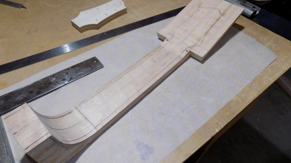
Now we can cut the neck to width on the bandsaw, leaving about 1mm to sand down accurately
Start the process - shallow vertical lines along the heel - on the table saw
Then do the neck side lines, starting with those groove-cuts
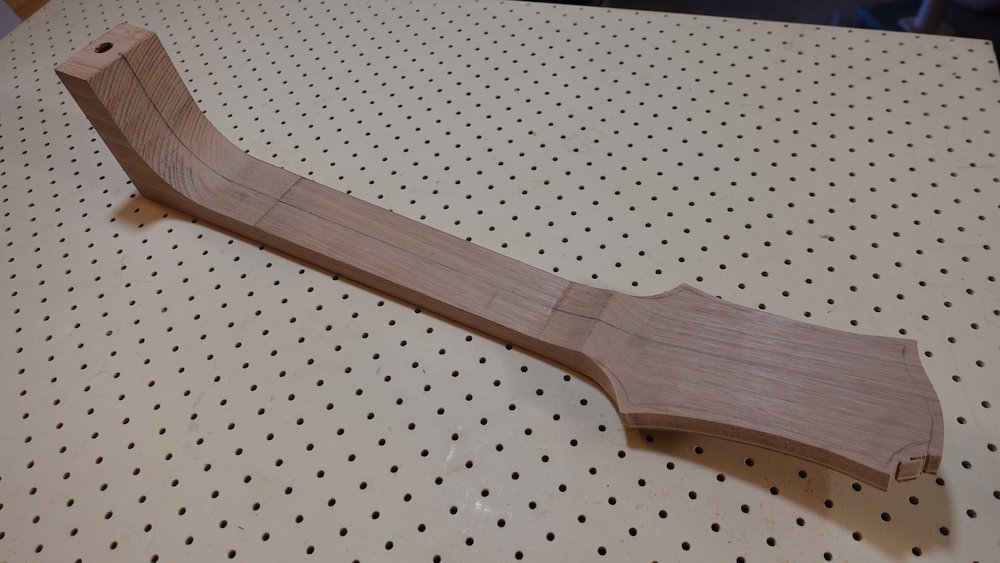
Neck and headstock rough cut, bottom |
Neck and headstock rough cut, top |
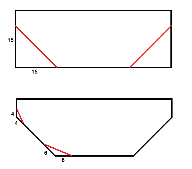
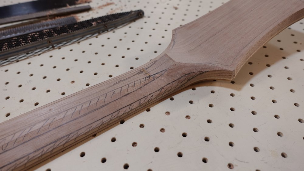
Carving the neck shape - facet method, assume 16-17mm neck thickness,
Aiming for a nice "C" shape
NB: when I am for a "C", I usually end up with a "D", as we will be narrowing the neck edges slightly
Don't be afraid of removing quite a lot of material!
First facets 15mm into the back, 10mm up the sides of the neck (9 at the nut?), flaring to 15mm at the heel
This will leave 6mm of vertical timber each side of the top of the neck
Second facets 4+4 (moving out from fretboard) and 6+6 (along the inside towards middle) - two of each
This will leave 2mm of vertical timber each side
Note that this seems "too much". but our neck is wider than it will eventually be...!
Neck facets |
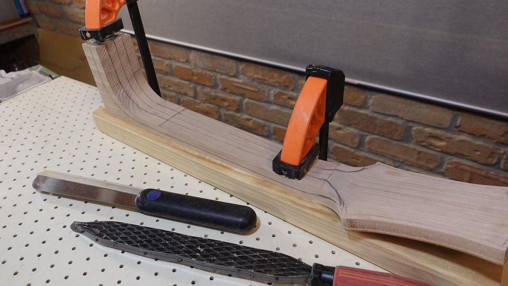
"flare" facets outward around volute and inward at the headstock - don't overthink it, it's pretty easy.
Smooth remaining facets, sand out rasp lines
Use Shinto saw rasp for straight sections, curved rasp for heel curve
Remove some of the scratches with a regular wood file
Avoid using scraper to remove rasp marks on end-grain - it bruises the grain, affecting how it absorbs shellac, resulting in uneven colouring
First facet lines |
First facets cut |
Second set of facet lines |
Second set of facet cuts |
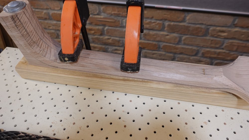
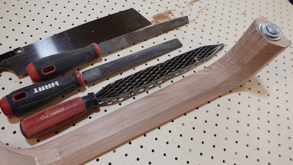
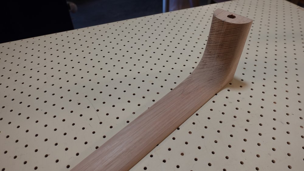
After cutting the three sets of facets, round everything over with a wood file
Coarse sandpaper to move closer to finished surface
Around this time, if not done already, re-transfer & cut headstock shape (leaving 2mm extra) using bandsaw & belt sander.
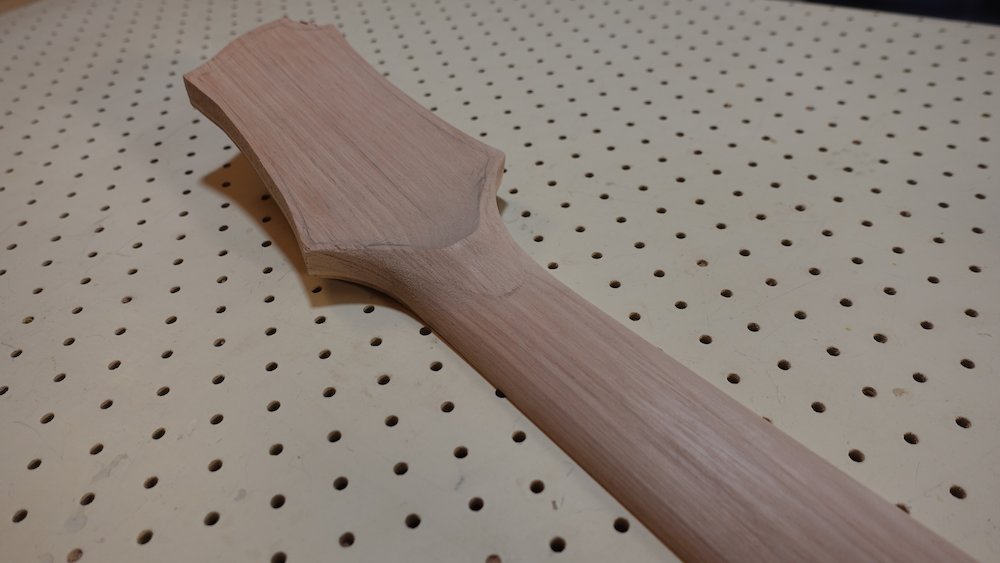
Neck shaped and smoothed: heel end |
Neck shaped and smoothed: headstock end |
Starting fingerboard
Overview:
mill timber to blank
cut proto-radius bevel facets using drum-sander sloping jig
refine radius with sanding block
Mill Merbau / Jarrah / Spotted Gum to 6.5mm, 66mm wide
Rough cut lengths
25.5" scale |
510 |
24.75" scale |
495 |
34" scale (bass) |
650 |
Rough in radius using drum-sander sloping jig
Draw scribble lines all over the surfsace
Make two sets of passes through the drum sander, rotating the work lengthwise
We want the two bevels, each being about a third of the width wide
The pencil scribbles allow the depth of cut to be judged accurately
Finish radius with 11" radius sanding block
Fingerboard bevels cut using slanted cradle jig |
Fingerboard profile using radiused sanding block |
Sides
Overview:
Mill sides and bindings stock
Bend sides and bindings
Laminate sides
Trim sides and fit into solera mould
Trim top of sides to a perfectly flat (and square) profile
Mark back-curve profile onto sides, then trim down to that line
Sides philosophy
Since kiln-dried timber is more readily available (and therefore, more choices with respect to grain, quarter-sawn, etc), we have chosen to go with it.
Kiln-dried timber is however much harder to steam-bend, and therefore needs to be milled to ~2mm
That's extremely thin at the best of time, but our steam bending process (with Tasmanian Blackwood, at least) of that thickness leades to lateral waviness
We therefore use a laminating process, to get adequate robustness, and allow sanding out the waves.
Originally I used plain old radiata pine for the inner layer, but I've switched to Macrocarpa
Waviness
Steam bending Tasmanian Blackwood, especially a 2mm thin layer for lamination, introduces waviness across the grain.
Usually 2mm is enough for this to be sanded out before cutting the binding channels.
However, if the bindings turn out to be too shallow, or other unexpected situations, we can end up sanding through the outer layer.
Milling sides stock
Mill to: 2mm (two sheets per side, to laminate to 4mm)
Bass |
155 x 950 |
GP |
120 x 850 |
Parlour |
113 x 800++ |
Those measurements assume near-perfect placement in the bender, allow a little more if unsure
Blackwood can be adequately steam bent |
Macrocarpa is an ideal choice for the inner layer |
Side bending
Assume
mould is in Fox bender with lower bout to the left
if there is a colour gradient across the side stock, we prefer darker toward guitar back
Then
Non-cutaway side: Darker side is to the rear
Cutaway side: Darker side is to the front
NB: New aluminium foil each time! Four layers on wide pieces (bass)
Aluiminium foil stops steam from escaping, and protects against iron contamination (from shim-stock in bender, and filings from when we made the truss rod). Iron reacts with hot, steamy timber and stains it irretrievably black.
Laminate each pair backwards, so blackwood "show" side is protected by what will be the inner layer
Shim stock process
Steel shim stock protects the timber by evening out bending stresses and heat
Under the wood: one layer of aluminium flashing, sprayed with black engine enamel, to better absorb heat lamp energy.
Aluminium is also bendier, less springy, placing less stress on the bent sides when removing from mould
Following that: one layer of 1/100th" steel shim stock
Over the wood: two layers of steel shim stock, but the outer one only over the waist and cutaway area
Heat top shims with heat gun while operating the Fox bender.
Order of operation:
Tighten waist press screw to keep mould and work steady
Make sure work is parallel with sides of mould
Measure so that the work piece will extend about 40mm past the end of the bottom of the mould's lower bout
For all the following steps, play the heat gun over the exposed top shim stock, to help heat the workpiece
Bend down the lower bout, keep it in place with the spring clamp
Bend down the upper bout, keep it in place with spring clamp and/or cutaway press screw
Slowly tighten waist press screw
If making cutaway sides, even more slowly tighten cutaway press screw
Leave work in the bender with lamps on for about 5 minutes, then let them cool down for about 45 minutes.
After removing them, allow each piece to dry thoroughly before next steps
Consider clamping them in the laminating mould to dry, to reduce springback
The mould used to bend the sides |
A Fox-style side steam bender |
Pre-heating sides |
Steam bending non-cutaway sides |
Steam bending cutaway sides |
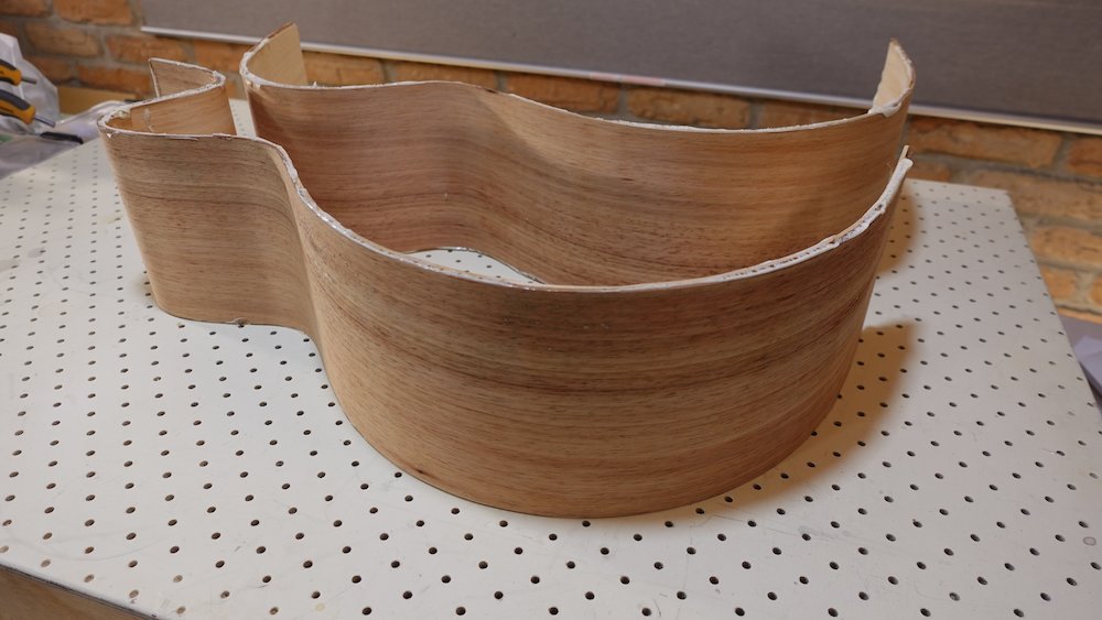
Bent sides after allowing to dry |
Also
Do the bindings while the Fox bender is set up
Three layers, accent colour on the inside
See bindings thickness plan at top of this documnent (Milling bulk stock in advance)
Make sure grain is straight along the bend dimension
Bend bindings in two batches per side
Thicker layer can be pressed hard, as we need it as tight as possible
Thinner layers need gentler pressing, so they don't compress into thinner sections at curves
Bindings ripped and milled |
Bindings bent using same process as sides |
Side Lamination
Place side pairs in laminating moulds, and trim off excess that otherwide prevent moulds from standing on workbench
Laminate pairs in laminating moulds
Radical decision: use Polyurethane glue!
fills gaps due to inadequate clamping
(Aliphatic glues, ie Titebond, produce voids, even with the best clamping)
Procedure
Put masking along sides of both mould and clamping caul, extending sideways
Apply glue sparingly!!!
It is critically important that the sides are perfectly aligned with the mould, clamping tight from one end to the other can cause this to "creep in".
Loosely fit all clamps, check alignment, then tighen
Note that the masking tape may make this problem harder to see
Too much squeeze-out makes extraction from mould tricky (hence masking tape)
If any squeeze-out has gotten onto mould, remove from mould *approximately* after three hours (depending on weather/temperature),
while glue is soft enough to separate easily,
but inside the lamination, strong enough to hold
NB: if taking the sides out of the mould early, put the cutaway side back in afterwards, and reclamp
- tight - so that there won't be any spring-back due to soft glue (which then hardens, cementing the wrong shape!)
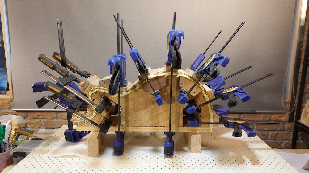
Gluing the sides for lamination, see laminating moulds to the rear |
Laminating non-cutaway sides |
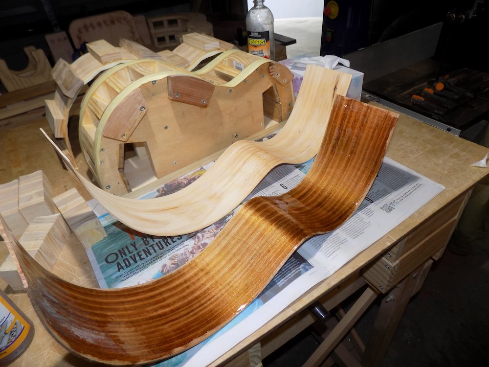
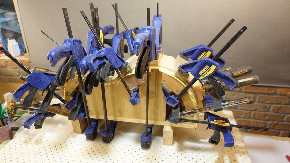
Laminating cutaway sides |
Sides laminated |
Fitting sides to solera mould
finalise neck-width at body-fret, create shim between solera mould-halves so cutaway-edge-to-centre is half that
Do not skip this step - solera moulds are a little thin on the neck joineven better, glue permanent shims for the standard neck width, so that we only have to shim for 12-string (or 5-string, in the case of bass)
Model |
Neck width |
6-string |
56 |
12-string |
59 |
Bass |
58 |
Fitting sides into solera mould is tricky, follow these steps carefully
Manually estimate cutaway end, as it will not fit into mould until near-perfect
Cut outside that estimate, fit inside and see how much needs to be trimmed so cutaway curve matches solera as closely as possible
Again, cut slightly less than that, repeat until satisfactory
Fit both pieces inside their respective half of the solera mould
Mark how far the tail each end extends
Cut 5mm short of that line
Attempt to clamp the two halves of the solera mould together
The tail will be out by about 10mm, mark how much needs to come off each side
Cut slightly less than that off and reclamp
The neck end will be way out, measure the gap between the two neck-ends of the solera mould
Cut that much minus 5mm from the non-cutaway side
Reclamp, check if solera mould can clamp together tightly
Also check verticality of sides around perimeter
Keep cutting a little at a time until perfect
A misaligned centreline at the tail end is quite OK, it will be hidden by tail strip and access port cover
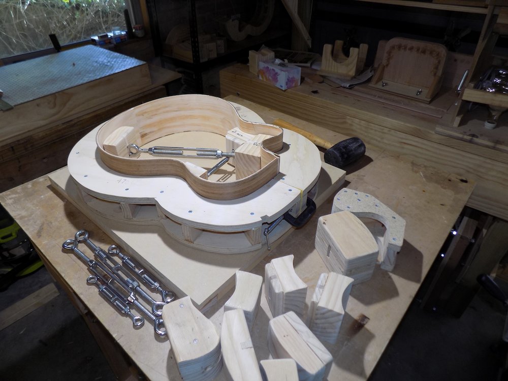
Depending on how secure the fit is, out-pressing turnbuckle clamps may be needed while cutting front and back profiles, and gluing access-port frame and neck block
Sides trimmed and fitted in the solera |
An assortment of solera turnbuckle clamps |
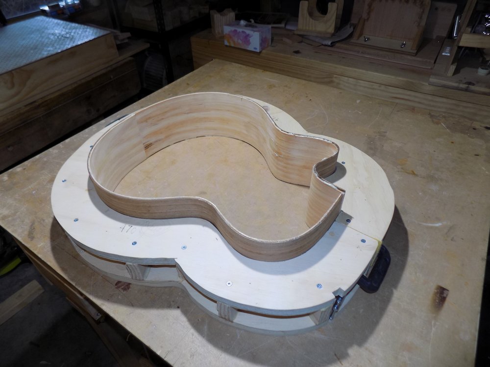
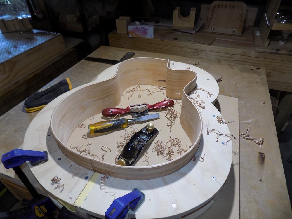
Trim top of sides to create soundboard edge
if sides are loose, consider gluing a temporary joiner piece to the place where the access port will be cut out
Spokeshave time
use laminated MDF reference flat surface
raise frame slightly and evenly
make sure every point along the sides are vertical (use set square)
slide a pencil around the inside perimeter, drawing a line
shave and plane to that line to get a perfectly flat top edge
edge can be checked with MDF reference surface
sticking sandpaper to MDF surface with double-sided sticky tape can zero in final flattening
NB: we only need it flat so we can measure the curved back profile points
the actual top profile will be adjusted to a more complex curve using a very shallow spherical sanding dish - later
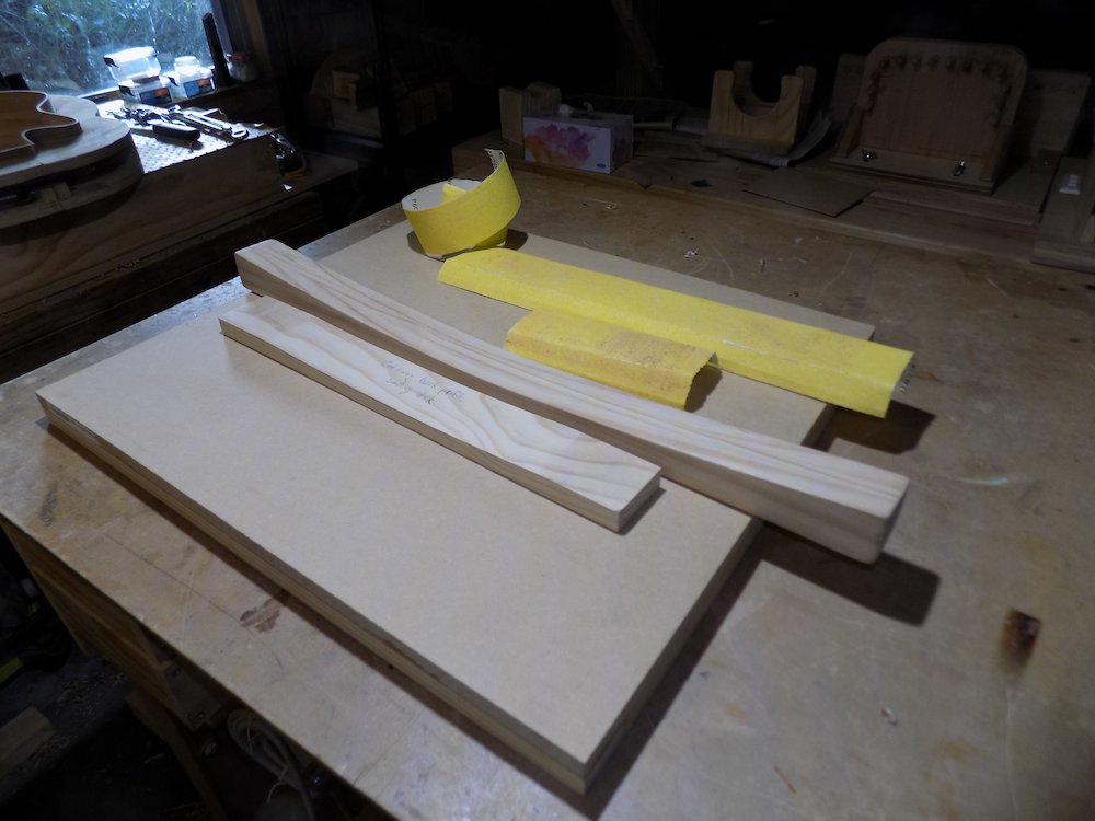
Profiling sides: flat for the top, curved for the back |
Curved sanding sticks used in side profiling |
Trim bottom of sides to create curved back profile
Position |
Bass |
GP |
Parlour |
Tail |
144 |
110 |
103.5 |
12% |
147.5 |
113 |
106 |
25% |
149 |
114.5 |
107.5 |
37% |
150 |
115 |
108 |
50% |
149 |
114.5 |
107.5 |
62% |
148 |
113.5 |
106.5 |
75% |
144 |
110.5 |
103.5 |
87% |
139 |
106 |
99.5 |
Neck |
132 |
100 |
94 |
Take care around cutaway - height *increases* towards centre!
two-dimensional curve
longitudinal curve governed by curved sanding stick
lateral curve much less than sanding stick curve,
lateral curve near cutaway with shorter, shallower sanding stick
This can be roughed in, and finessed later (after kerfed linings attached) with curved sanding sticks
If a well-shaped result is achieved while still too high, keep it - it is much easier to cut down the flat topside to the correct size
Turn work over to check "roll" of edges against flat surface
Avoid any "sharp" spots (tilt rather than roll), they will make fitting bindings more difficult
There will be a very slight tilt spot at the cutaway, as the sides curve towards the centre
In paricular, the measurements above have a sharp spot in the middle that is intended to be rounded over
Sides marked up for profiling |
Rought profile cut, switching to sanding sticks |
Back profile from neck end |
Back profile from tail end |
NB: this is from the most recent build, which turned out a little flat in the middle.
My next build will use a hybrid of that profile and the previous build
Previous profile (neck end) |
Previous profile from (tail end) |
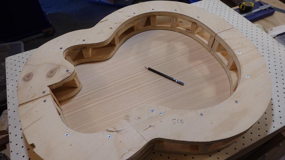
Gluing neck block
Overview:
Place sides onto soundboard clamping mould to plan the fit to be perfectly located and square
Mark up neck block with the three curves than have to be cut
Cut and sand those curves
Glue neck block to sides
Mark guitar centreline on various faces of the neck block & neck support tray
Place sides onto soundboard clamping mould so that we can position the neck block and check squareness and lateral position
NB: neck width at body fret needs to be considered
need centre of tongue-channel to be 0.5*neck width from outside of cutaway face
(see table above)
if the solera mould had been correctly used, this will be the mould's join lines
leave the support tray 0.5mm proud, but the heel cap end can be flush
Mark the three curves or angles that need to be cut on the neck block
One on bottom, to fit into curved back - flat OK at first
One at the side, to fit into cutaway - will need to be sanded concave
One at the mortise end, to fit the tiny amount of non-cutaway-side curvature
Cut just shy of the lines using the table saw
Finish them by hand by various means
Use the narrow convex sanding block to match the shape of the inner cutaway
Note that some of that sanding will on end-grain, and sandpaper will cut it less than side-gain
use a sharp, narrow chisel to even out the load
NB: Double check that sides (especially around shoulder/cutaway) are square to the front. Gluing the neck block commits to the that alignment.
NB: Double check that neck block, when clamped in, is square with the body centre line
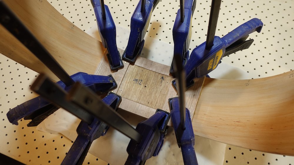
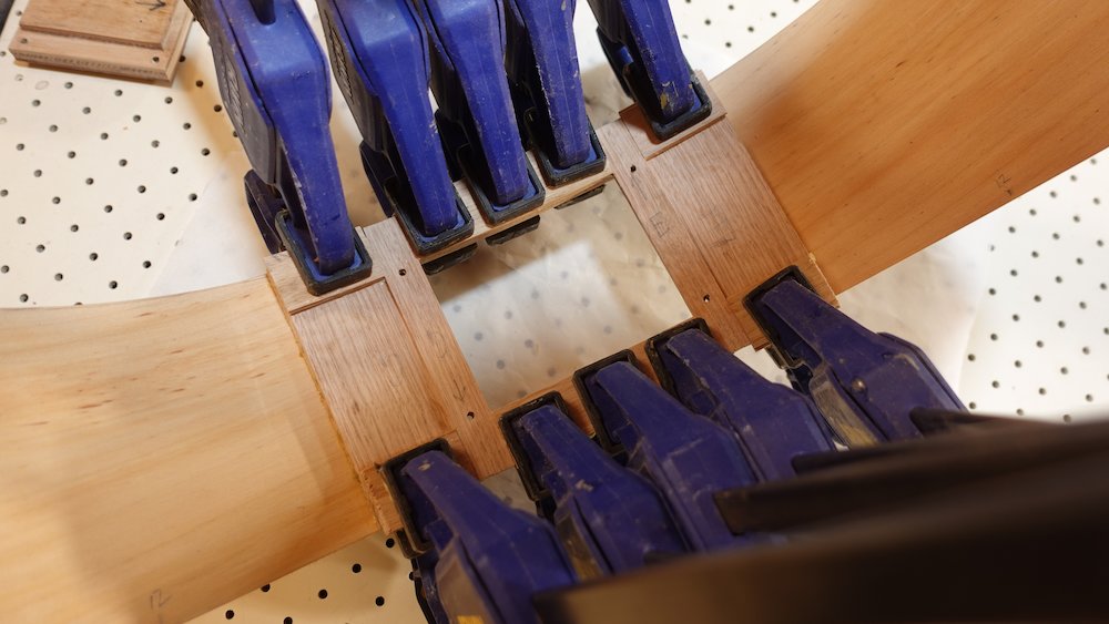
Glue and clamp
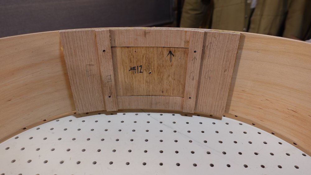
Neck block cut and contoured |
Gluing the neck block in place |
Bolt-on neck block glued (top) |
Bolt-on neck block glued (bottom) |


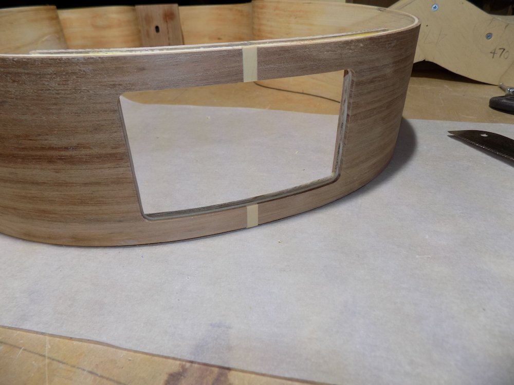
Gluing access port
Overview:
Trim access port layers
Glue middle access port layer to sides
Cut tail slot and fit tail strip
Create access port hole: hole-saw, then flush-cut router bit
Square out corners with rectangular file
Finesse middle cover layer so it fits into hole
Glue in inner access port layer
Check whether cover curvature matches guitar, make any required adjustments
Assemble all layers together (two sets not glued), cover screwed in place (for alignment)
NB: cover can't be in place if "temporary joiner piece" glued at seam
Position, centre vertically and horizontally, mark layers, trim leaving ~1mm top and bottom
Glue outer piece, so that the extra 1mm is evenly distributed top and bottom
clamp the outer ends with same convex clamping cauls used when laminating access port frame upright components
Don't bother sanding it flush yet, wait for the kerfed linings.
Mark true centre, top and bottom, tail and neck
Remove from mould!
(possible thanks to over-engineered sides and single access port frame layer)
Cut ~2mm deep slot (dado style on table saw), then cut and fit tail strip
(much harder to do later, after we cut the actual hole)
Also, end-tear-out is less of a problem now
(Surface tear out can be managed by decent blade and/or slow feed speed)
Centre over true centreline (might not be sides join-line)
Before finalising width, put back in solera to check alignment
Glue in, then trim and level
It is quite acceptable to cut the tail strip in two so that it just covers top and bottom, as the access port hole is about to be cut out
Using drill, hole-saw and router(flush bearing bit), remove material from hole
Drill and hole-saw: remove the bulk so the router does less work
Router: flush bearing bit to rout sides to line of access port outer layer
Remove any glue on access port sides first, so routed line is straight
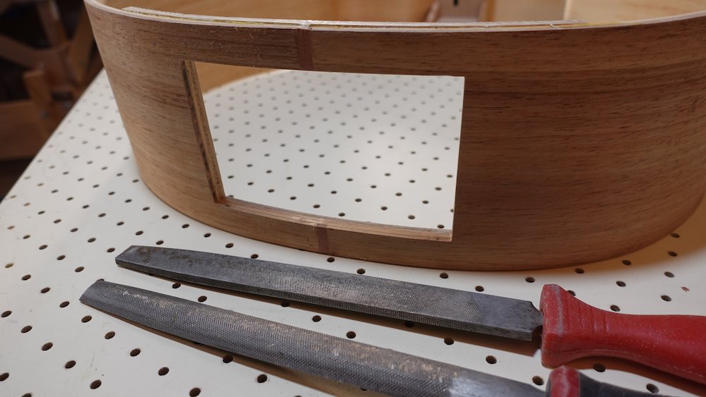
Square out corners with rectangular file so cover fits through
a regular rectangular fire, while slower than some alternatives, is safer:
Make a notch in the rounded corner, then work it outward and downward until both edges are straight.
The end result of this step is that the cover should fit through (and sink into) the hole, so that it is flush with the inside (ie, to its final depth)
The steps involved include
Making sure the outside hole perimeter is straight, square and it true corners
Fitting the cover in as best as possible, then putting your head inside the guitar, looking in a light source, and noting tight spots
Drawing lines with a pencil to show when you are filing parallel to hole edges
At the very end of the process, it might be appropriate to sand the cover itself, particularly to adjust the angles of the two upright edges
Trimming access port |
Gluing frame middle layer |
Gluing tail strip |
Routing access port hole |
Access port hole routed |
Access port hole squared out |
Fit inner layer (using partially completed cover to align)
since we need to use the cover to align it properly, we cannot do this inside the solera mould
this introduces the risk that the final curvature might not quite match the mould, or the cover itself
Problem of inner layer springback
Clamping outside solera mould may change tail curve
Access port cover curve may no longer match access port frame
Current procedure
After gluing in the middle layer, inspect:
The resulting curve of the sides+middle layer
The curve of the as-yet-not-glued-in inner layer
The curve of the cover
Take remedial actions as required:
Relax or tighten curvature of middle layer before gluing by wetting, heading, clamping
Relax or tighten curvature of cover (wet / heat gun, clamping)
Consider whether the laminating moulds need to be remade/adjusted before laminating in the first place
Also, consider
just how different is the curve?
Will it still fit into the solera?
Remember cover will be bolted in place, inside solera when attaching back and soundboard
Will the difference in tail curve be noticeable when the guitar is complete?
Previous approach (not recommended, not shown in images)
rub some candle-wax around inside of cover
rub some candle-wax around non-glued surfaces of frame
put sides back in solera mould
leave cover in place while clamping
Mark sanded/trimmed top & bottom line, trim
Holes drilled yet?
Glue and clamp inner layer,
fit cover (including bolts) to ensure the two layers align
note that some of the inner layer face does NOT require glue!!!
use frame-to-sides clamping caul with exact shallow curve at each side of the frame
remove cover immediately so it won't get stuck by glue squeeze out
clean off all squeeze out from cover and inside edge of frame
Gluing inner layer of access port |
Door removed after using it to align the glue-up |
Finish access port
Overview:
Create outer layer of cover: one support piece, outer show piece & border strips
Get it to fit
Laminate outer to cover (using index pins)
Glue in the two nut strips to the inside of the acces port frame
Glue in extra strips filling/covering the nut strips (now that the top/bottom borders are thinner)
Prepare the following
outermost layer (actual show piece), ~1.7mm, curved
second-outermost layer, <2mm, also curved
some strips of border accent wood, ~12 x 2mm, straight
To create the outermost lamination
Carefully trim/sand second-outermost so that it fits into the hole,
OK if it doesn't quite go all the way in against the coverCut border strips with the top and bottom pieces full width and the uprights fitting between them
Cut the outer centre panel so that it fits between the border strips
Use sacrificial backing, as tear out affects the show face
Glue and clamp top and bottom strips and centre panel
The cover can act as a clamping mould for this step, since the top and bottom border strips are not pre-curved
When dry, excavate any squeeze out from the channel where the side border strips are to go
Glue and clamp the side border strips
sand the border strips flush(ish)
redo the fitting, as perimeter will have changed...
This almost final perimeter fit
trim to within ~0.5mm on table saw, cutting "inwards" to prevent tearout
sand top and bottom so that the piece fits
for each side, slide up, inspect gap - there will be some unevenness
sand out until each end slides up perfectly
check overall width, reduce and reprofile appropriate side-end as needed
Gluing centrepiece and top & bottom strips |
Gluing side strips |

Before proceeding, check that inner cover curve matches guitar
if it is too shallow, consider shimming the two side edges
if it is too deep, consider shaving down the two side edges
also consider wetting / heat gun / clamping to adjust curve
At this stage, it may turn out that the cover doesn't sink in as far as it should
This may lead to the outer layer being too proud, and requiring too much levelling
Especially if the two outer layers are too thick
Consider very gently sanding the outside of the cover, to thin it a little
Don't overdo it, glue squeeze out on the cover show face (panel, border) will require some levelling
Tack two thin nails through inner cover, poking outwards 2mm
Angle (relative to the curve) so they're parallel with each other (not flaring out)!
Fit inner cover
Press outer cover layer into place, impaling it against the two nails
Remove
Laminate outer layer, using nails as index for alignment
remove as much squeeze out as possible, as sanding/scraping/chiselling it from a fit-critical edge is not much fun
Remove nails
Fitting the access port outer layer |
Index pins (nails) to align outer layer of access port |
Extend five holes (strap button in middle, four countersunk screw holes at corners)
Fit cover in place
Screw four corner bolts through holes (apply some candle-wax first)
Glue in place the two nut-strips we made when laminating access port layers
Best done with cover in place, but need to manage squeeze out
Rub some candle-wax around inner edges of cover
Apply glue to inner face of nut-strips (if possible, not the parts exposed at the edge)
Position nut-strips in place
Tighten four bolts so they engage nuts and extend inwards
Clamp (bolts are only pulling against nuts, nut-strips are just sitting over them)
Gluing the access port outer layer |
Preparing to glue the nut strips |
Gluing the nut strips |
Finished access port (GP, Bass) |
Extra steps for Fat Parlour
(Optional on GP, not required for Bass)
Cut and glue in some extra strips around and over the nut strips top and bottom
This is because to make the access port high enough, there is not very much wood top and bottom
Most guitars have a solid tail block here, we've got this frame with a large hole in it
Building out frame top & bottom |
Finished access port (built-out frame) |
Hopefully end up with cover fitting, as well as the four bolts
Scrape and sand flush if any major level discrepancy (lots of further sanding to be done later)
Clearly mark centre lines on side frame
both ends, top and bottom, glue faces, inside, outside
I mean, it's so annoying when you have to keep working it out again...
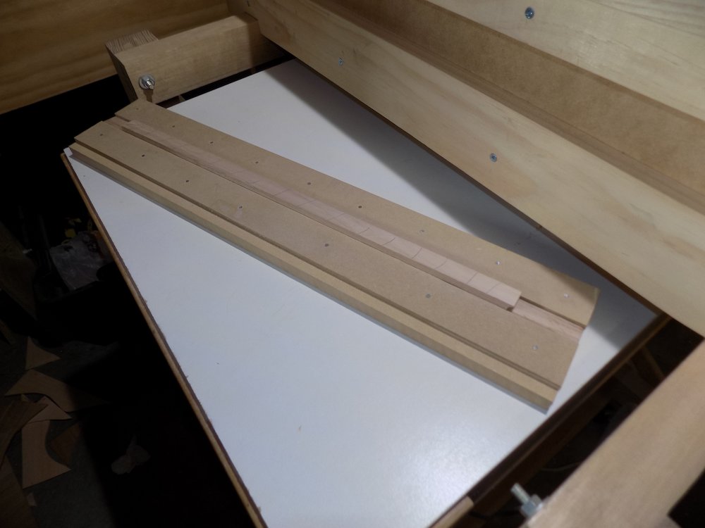
Kerfed lining
Overview:
Create kerfed lining
Glue it in
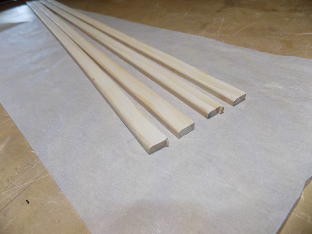
19mm stock, rip and mill to 7mm, the put a radius on one of the side edges
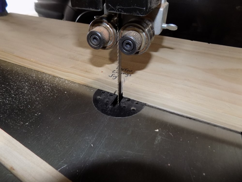
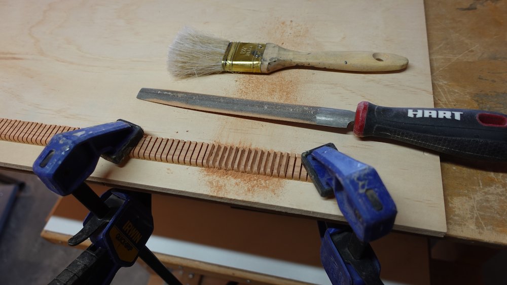
Bandsaw guide - slotted stop board,
use headless nail to get each cut "evenly" spaced lol
Also use bandsaw table extender
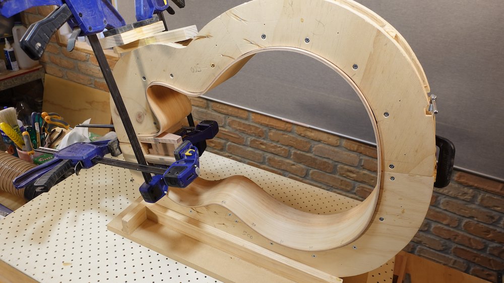
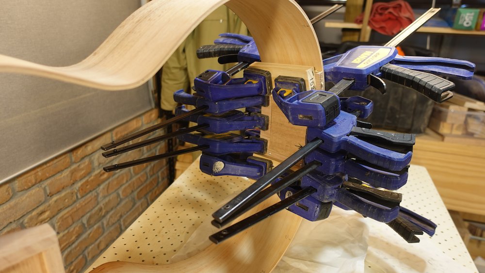
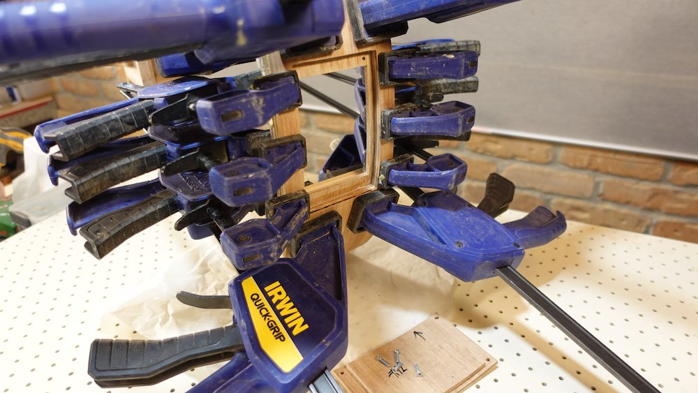
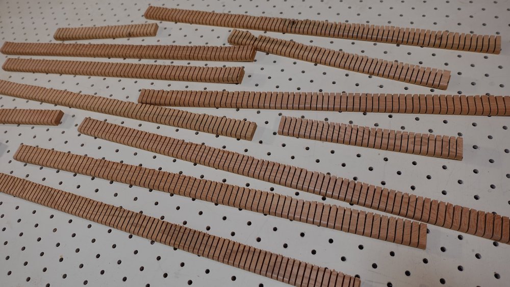
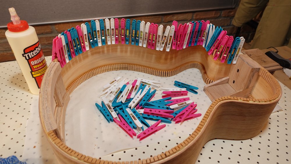
Cut and glue in place, top & back, clamping with washing clamps (see image)
NB: for inside the cutaway horn section, the kerfs will need to be widened with a file, beveling the blocks so they can pack closer together
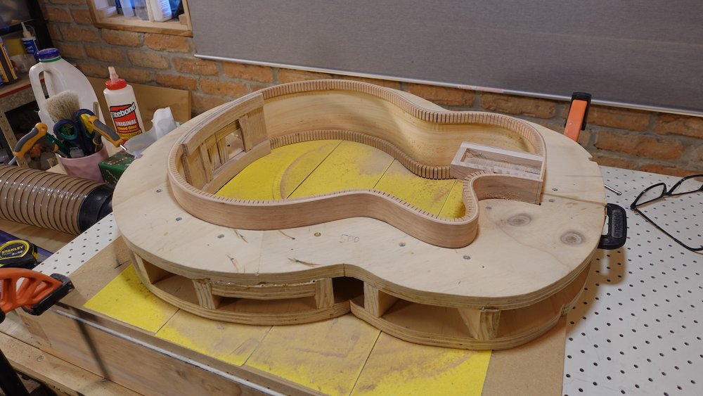
Using the Shinto (not band-sander!) trim to a whisker above already-prepared top and bottom profiles, then sand by hand to get perfect surface for gluing
Kerfed lining stock milled |
Bandsaw jig for cutting kerfs |
Kerfed linings cut |
Bevelling the kerfed lining for the cutaway horn |
Gluing kerfed lining |
Sides levelled ready for soundboard and back |
Bolt-on neck experiment (though this also applies in general for getting correct neck angle)
When levelling the soundboard edges of the sides, we want the extended "tray" of the neck block assemble
to slope upward slightly, corresponding to the tiny amount of curvature the soundboard will eventually have.Previous attempt: when extending the tray line along the length of the guitar, have it end 5mm above the tailblock edge.
This makes the cutaway a bit problematic - the sides have to be higher to "meet" the higher neck tray.Current attempt: use a 9m (29.5ft) radius sanding dish, but in a sort of hybrid way:
we only really want the spherical side profile at the neck-cutaway area, we want it pretty flat everywhere else.
Resawing, milling, butt-joining back and soundboard
Overview:
Cut, rip, resaw and mill bookmatched boards for back and soundboard
Joint the edges with the angle sanding jig
Glue them together (show face up so we can clean off squeeze out)
Thickness them to required... thickness
Trace outline of back and soundboard, and roughly cut out on the bandsaw
Raw minimum dimensions (cut longer and wider for jointing and positioning leeway)
Model |
Length |
Width |
Board width |
Bass |
570 |
460 |
230 |
GP |
500 |
410 |
205 |
Parlour |
470 |
390 |
195 |
both pieces, both sides
Mill timber to 5mm
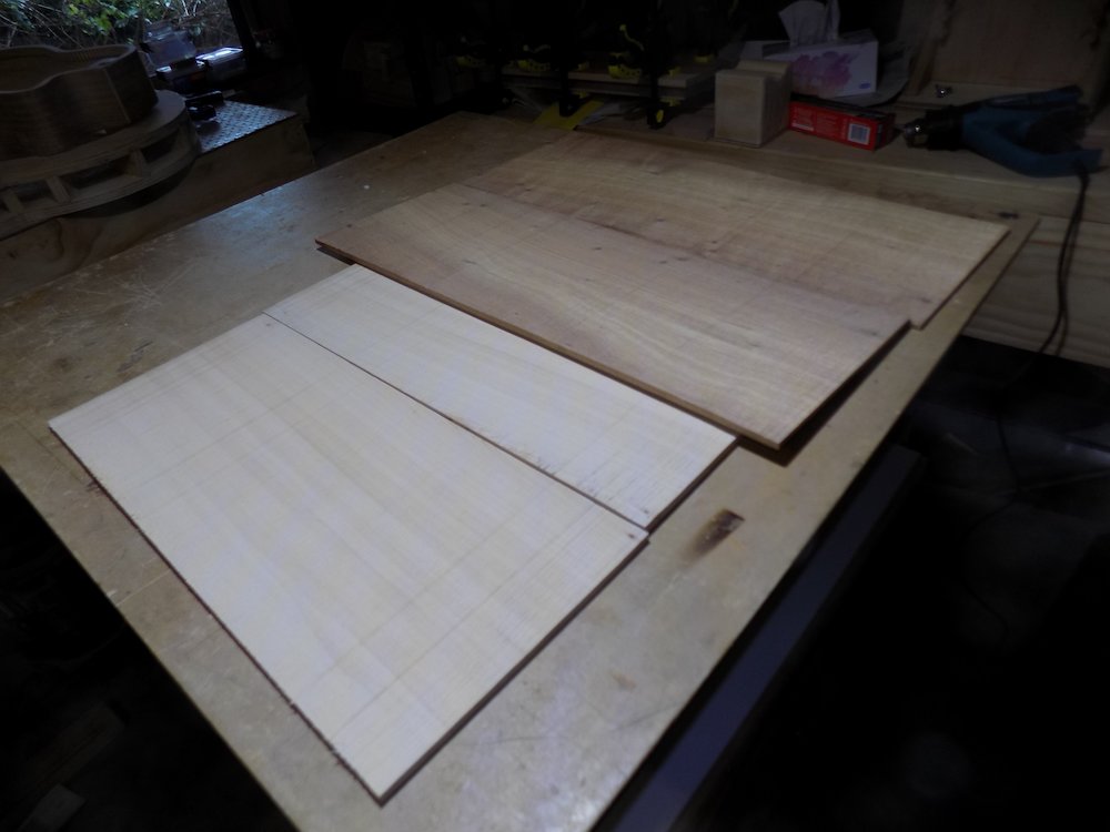
Resawing on the bandsaw - use resaw post, lock the fence down proper!
NB: pay special attention to drum sander scarring: particularly if using 60-grit sandpaper.
If perfectly parallel to the grain it can be overlooked, but with any lateral movement in the drum sander it becomes an eyesore that is very difficult to sand out, particularly on the soundboard.
A combination of 80 grit, plus some final low-friction passes on the show face, should be enough to keep it under control.
NB: if not butt-joining immediately, store boards clamped between two flat boards to prevent bowing/cupping
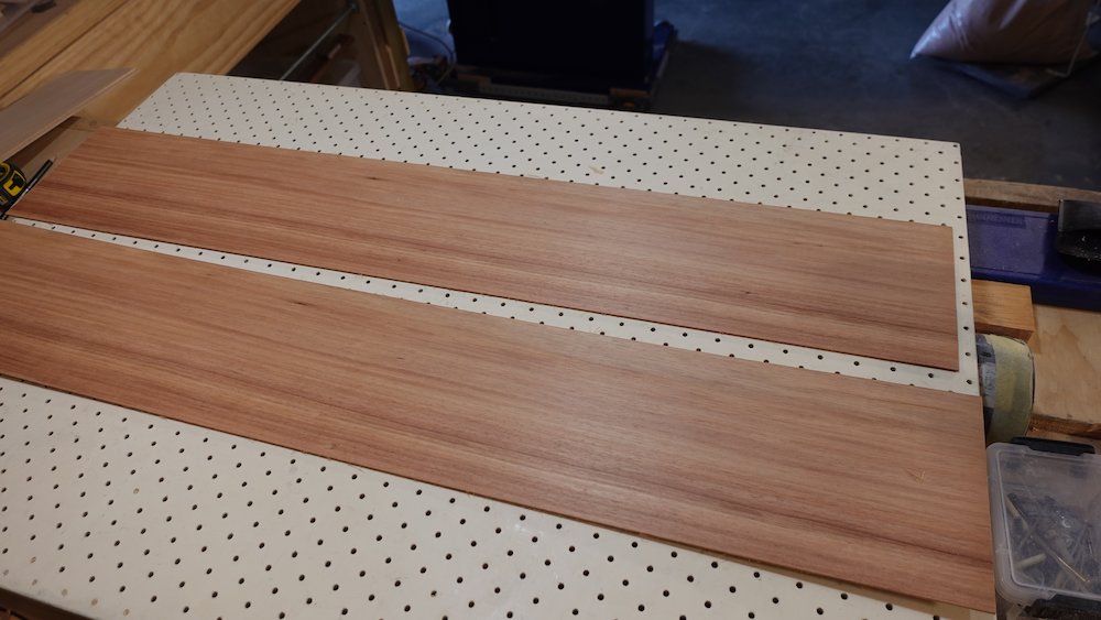
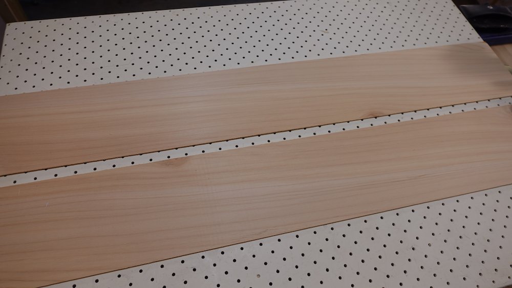
Resawn boards for soundboard and back |
Soundboard and back boards drum thicknessed |
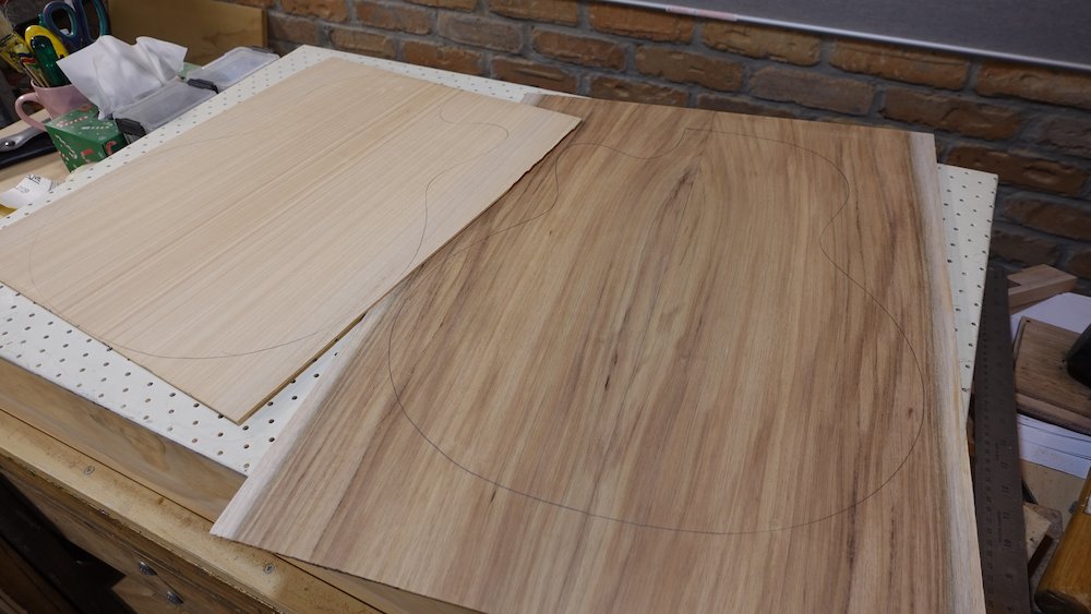
Before gluing we need to joint the edges.
If they are not reasonably square and straight, make them so with the table saw.
Then finish the job with the aluminium angle jointer sanding jig.
Jointing the soundboard to prepare for butt-join |
Preparing to butt-joining the soundboard |
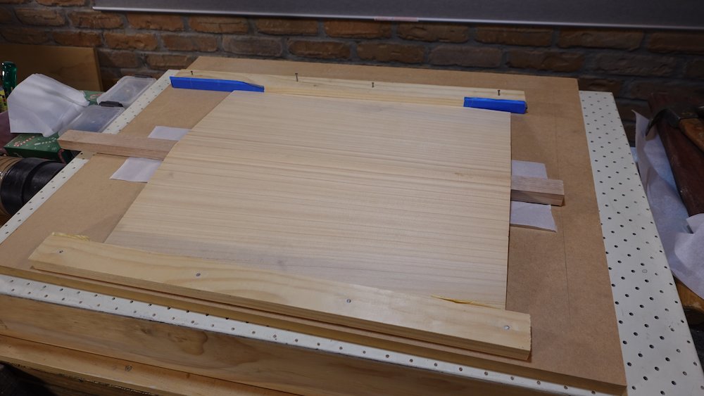
Butt-join using a sheet of MDF, nailed down strips of pine as edge stops
Cover MDF with oven paper where join line will be
Raise the two pieces along the join line with a piece of 19x42mm stock
Show face up
Position and nail down edge stops
Apply glue, align, then remove the length of stock and press down
Check joint alignment, clean off squeeze out (while pressing down to prevent them from springing backup)
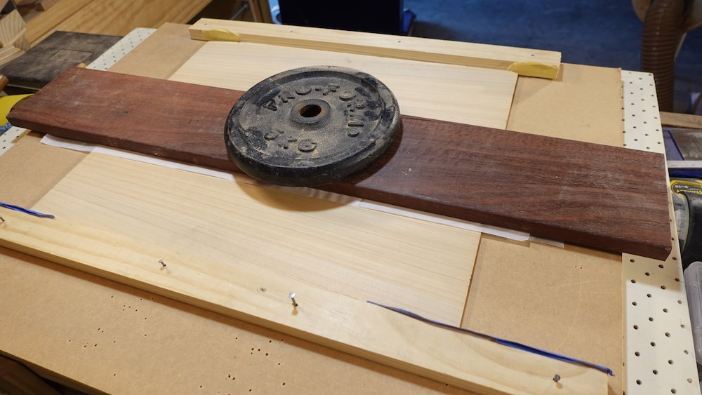
Cover with more oven paper, a hardwood board and weight
Butt-joining the soundboard |
Tracing the body shape to soundboard |
NB: after butt-joining, store boards clamped between two flat boards to prevent bowing
When dry, using mould, trace body shape outline (both sides, but lightly on the show faces!), cut with bandsaw, 5-20mm outside line
For guitars, this can be done after final thicknessing
For basses, consider doing this after the rough cutout
Leave flat sections at each end, so they can be pushed through drum sander with a piece of 3mm MDF
Mill to required thickness using drum sander
First mill non-show faces so that join line is clean and smooth
Then mill show faces so that join line is clean and smooth
Finally mill non-show faces (again) to width
Soundboard:
Celery-top: 2.8mm
Huon Pine: 3.0mm
King Billy: 3.4mm (less?)
Macrocarpa: 3.0mmBack: 3.5mm
Clearly mark centre lines
Body shape traced onto soundboard and back |
Soundboard and back outline roughly cut |

Bracing and fitting back and soundboard
Overview:
Prepare back and soundboard bracing pieces
Sand profiles into the base of those pieces
Glue in back braces
Prepare centre strips for back, glue in the middle three
Taper the back braces
With sides in mould, trace neck block & kerfed lining to inside of soundboard
Mark A-frame brace positions, trim A-frame brace pieces
Glue in A-frame braces
Taper the A-frame braces
Prepare bridge plate and sound hole backing support
If not bolt-on neck option, prepare neck-end support
Taper wing braces
Glue in bridge plate, hole support, wing braces and neck-end support
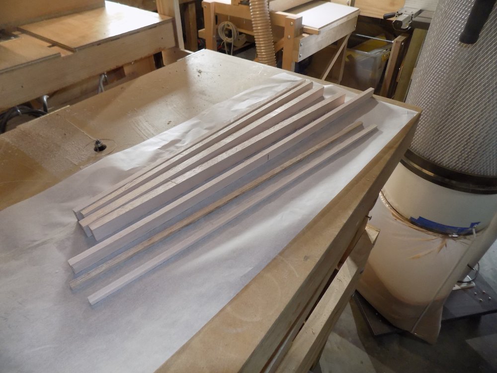
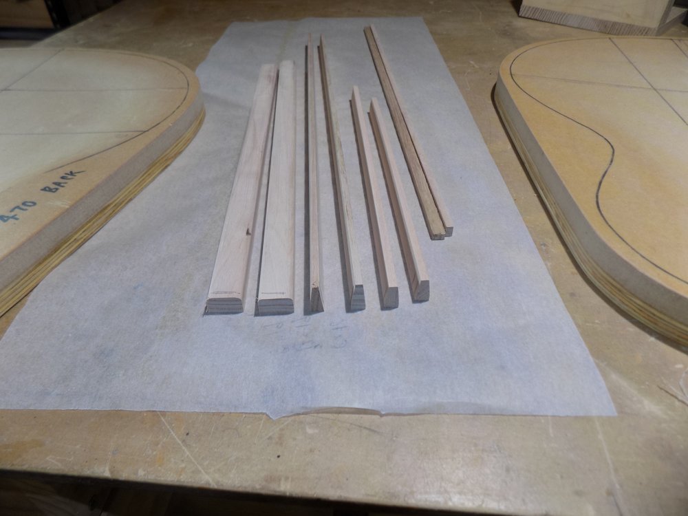
Prepare (rip, resaw and mill) back-brace sizes and positions
Four,
two x 8*16mm (vertical taper, neck end)
two x 12*19mm (rounded over, tail end)
Spacing (from neck)
Bass |
110 |
95 |
110 |
110 |
leaving 130 to tail |
GP |
99 |
86 |
99 |
99 |
leaving 117 to tail |
Parlour |
93 |
80 |
93 |
93 |
leaving 110 to tail |
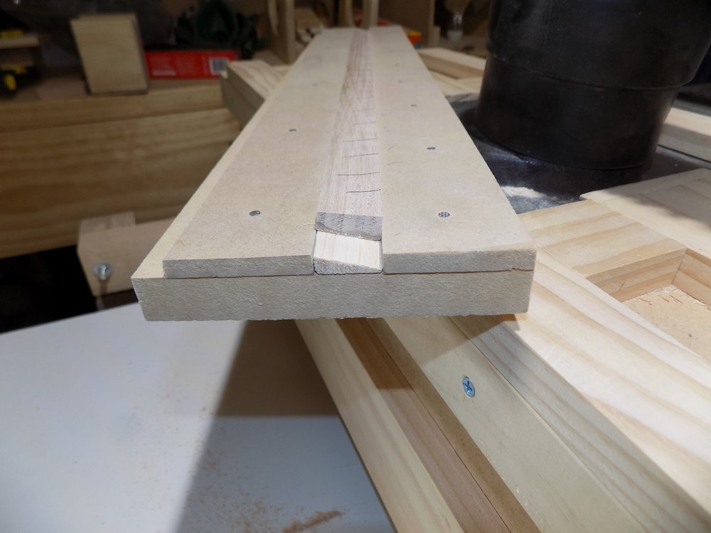
While thus tooled up, might as well mill stock for side braces as well
8x5mm, long enough for eight x body height
Bracing timber milled |
Bevelling bracing pass one |
Bevelling bracing pass two |
All bracing pieces sectioned |
Prepare A-frame soundboard braces size and positions
Two pieces, 8*19 (vertical taper)
from neck joint to a spread at tail of
Bass |
165 |
GP |
149 |
Parlour |
140 |
2 * 8*17..19 wing braces (rounded over) (outside of bridge to side)
Bass 165 |
GP 150 |
Parlour 140 |
Sanding profiles into braces
Rough-in the profile with (bandsaw?) and belt sander
Clamp sandpaper to moulds, sand until full profile is cut (no flat spots)
Use a holding jig to avoid stressing fingers
but only during initial hodding phase
finish with fingers so they stay seated, to avoid rounding over the bottom crosswise
If doing the wing braces, sand across the centre of the soundboard mould, and symmetrical is OK
Bracing preparing to profile |
Profile rough-sanded into some of the braces |
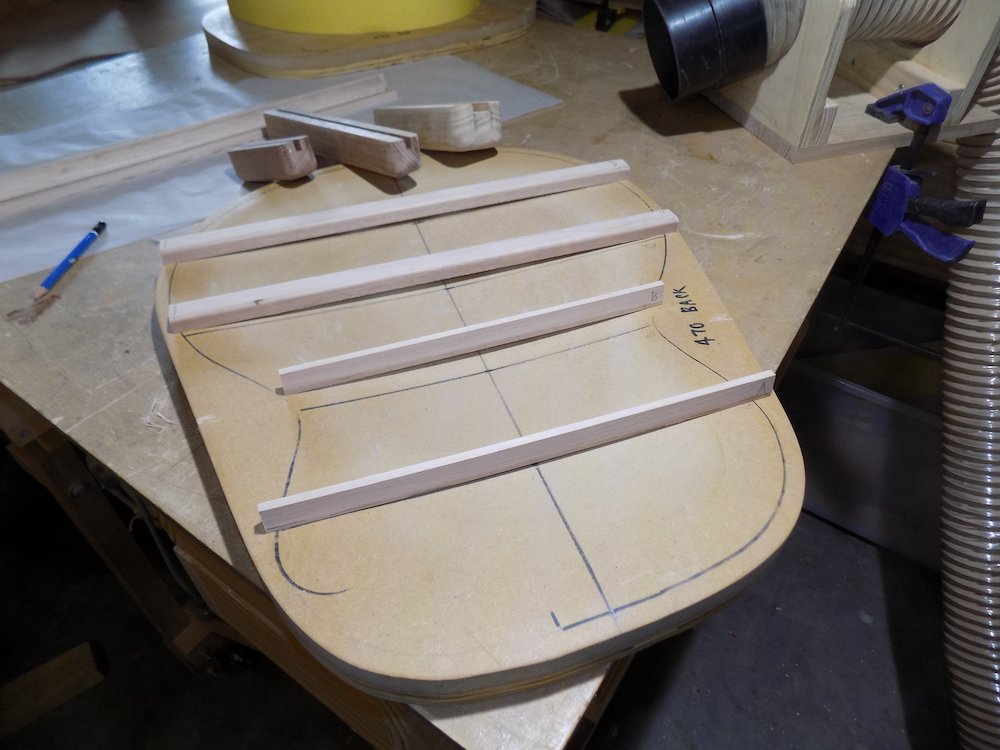
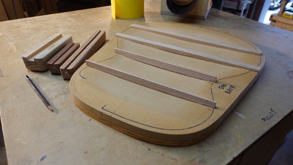
Fine-sanding the profile to one of the braces |
Profiling finished on one of the braces |
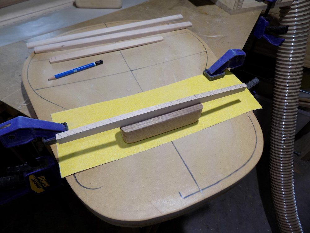
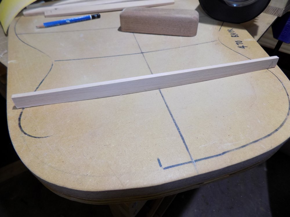
Fine-sanding profile to one of the A-frame braces |
All braces profiled |
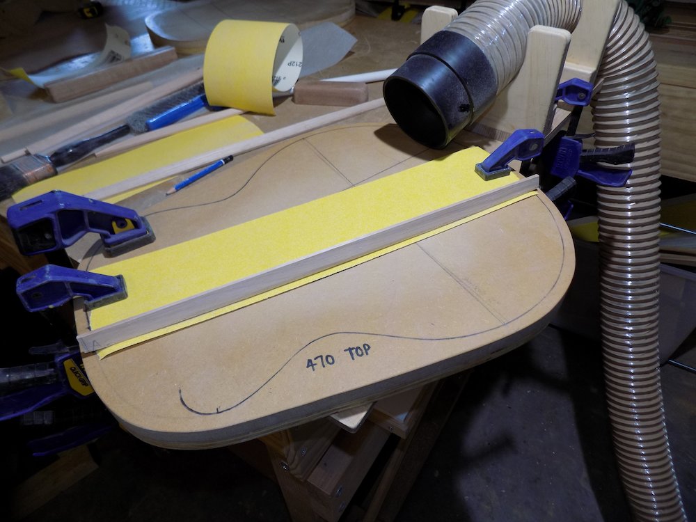
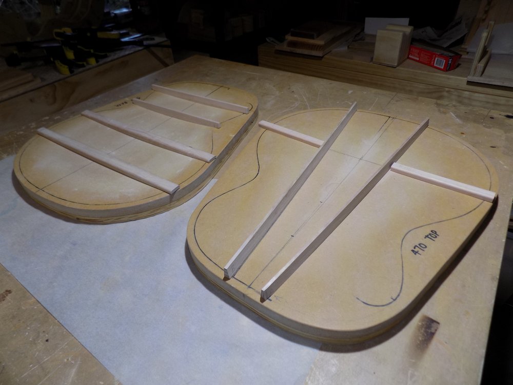
Planning back brace positions and gluing
Method: caul blocks and go-bar clamp at ends first, clean up squeeze-out, then do middle
Preparing and fitting centre-strips
Cut five lengths of milled 3-4mm cross-grain hardwood
30-40mm wide
NB: the outer two cannot be glued yet (length depends on neck block and access port)
The reason we glue the inner three pieces now instead of later is simply to make the back stronger during the next few steps
Round over edges, glue the inner three down centreline of back
Use go-bar clamps, same rods as for back braces (with 19mm cauls)
Gluing back braces |
Gluing (middle three) centre strips |
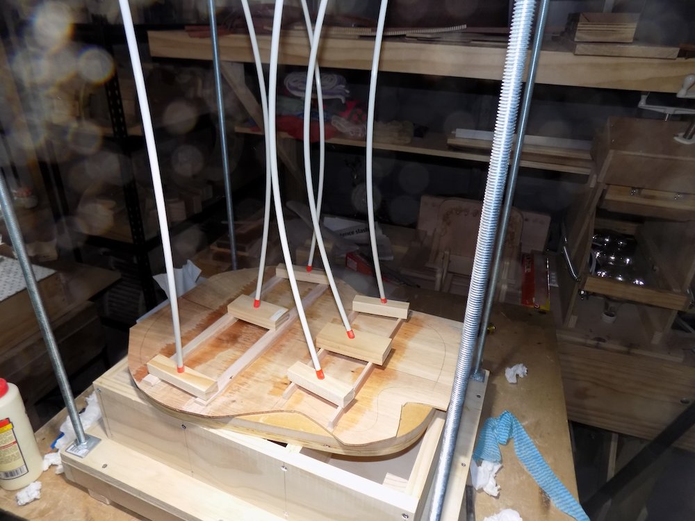
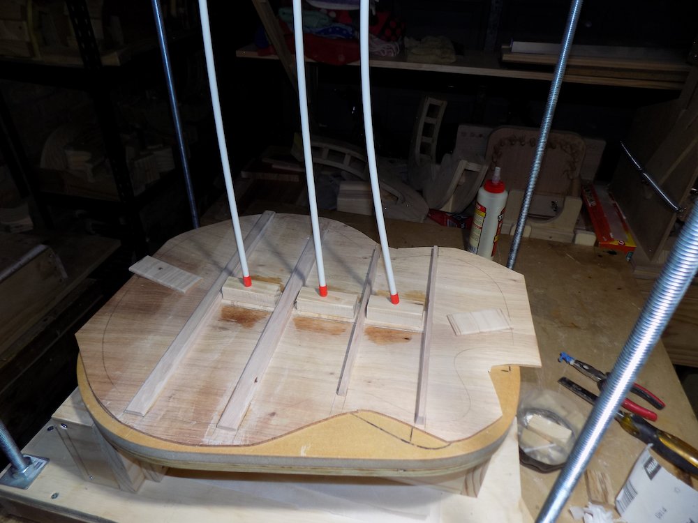
Tapering back braces
Spokeshave, plane, chisel, short block of scrap to check straight lines
Tail end pair: 50mm linear taper down to 1mm at perimeter
Neck end pair: 65mm linear taper down to 1mm at perimeter
Planning and gluing soundboard brace positions
Trickier
Put side frame in mould, with turnbuckle bracing if required
Trace out neck-block, cutaway-kerfed lining, access port positions - to the inside of the soundboard
Mark how A-frame braces need to trimmed to fit (and do so)
Glue: normal clamps at ends, go-bar clamps in middle as per when gluing back braces
For the bolt-on neck option
the non-cutaway side A-frame brace will be a bit of a pain to cut
we end up with a bizarre shard with complex angles (see image below)
don't worry, when we taper the braces, almost all of this will be shaved away
Tapering soundboard A-frame braces
Taper full-scale line (measurements next paragraph) to neck,
then from 19mm tail-ward of that line to tail
(ie around the wing braces)
aim for 2mm at ends
Scalloping: about 5mm dip midway, both ends
Tapering back braces |
Fitting soundboard braces (glued neck) |
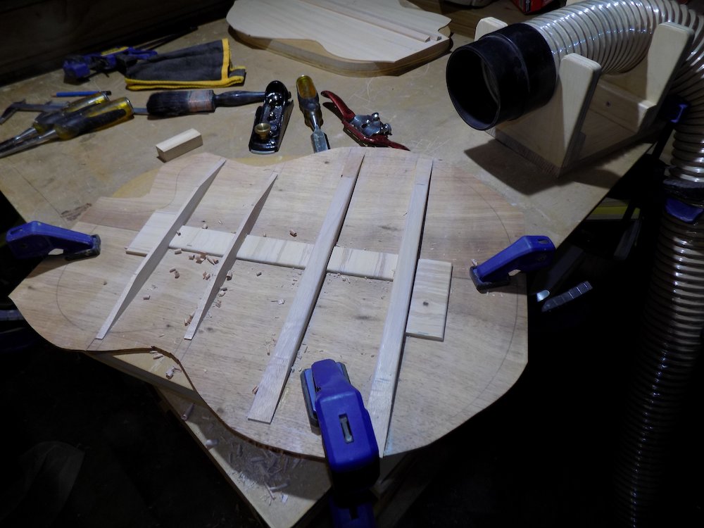
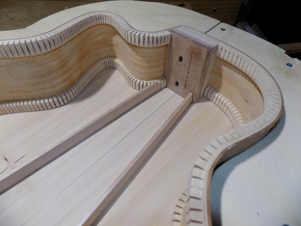
Fitting soundboard braces (bolt-on neck) |
The bizarre soundboard brace cut end |
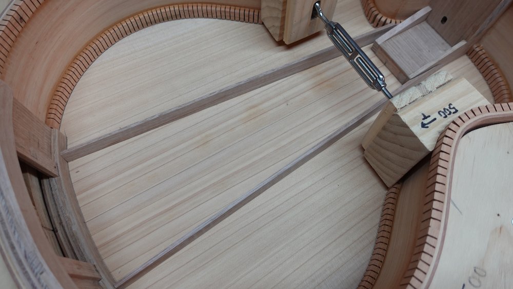
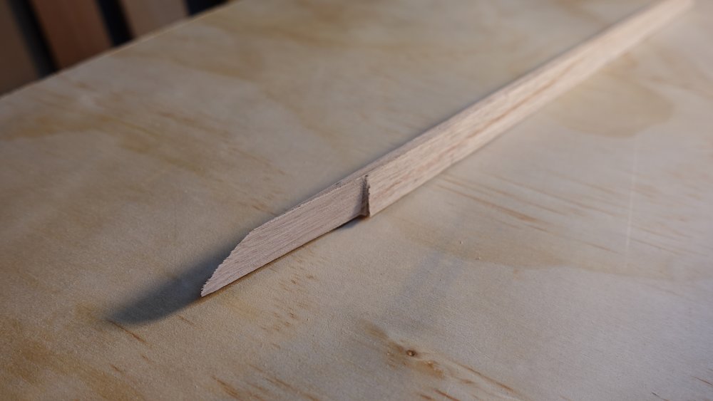
Gluing soundboard braces |
Tapering soundboard braces |
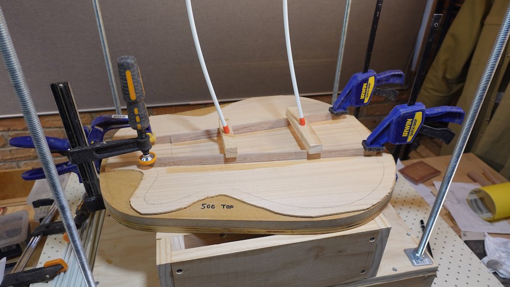
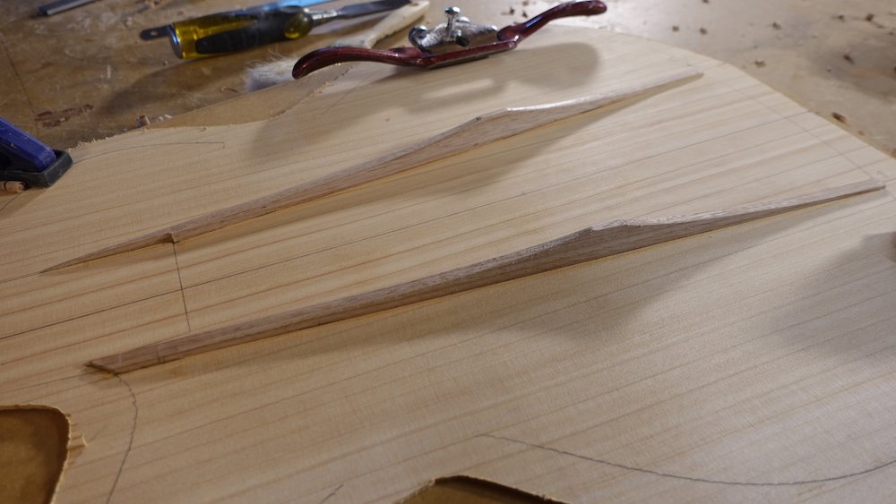
Preparing soundboard bridge plate
Body-fret to full-scale line
24.75 14-fret |
280.0 |
25.5 14-fret |
288.5 |
Bass 14-fret |
384.7 |
Mark bridge-line (full scale length)
Bass bridge is 52mm deep, guitars less than 50
- let's just say 50 for all
Cut 3mm bridge plate (slightly thinnger OK if hardwood), 75mm deep (will trim later)
Crosswise grain
Sand in a bit of a lateral crown to match dip in mould
(to reduce the bracing contours appearing when the soundboard is varnished)
Starting 12-15mm in front of bridge line, total depth = bridge_depth+10
60++ is probably about right
That 12-15mm extends a bit, but is good if fitting piezo pickups
wedged between A-frame braces
Trim depth after getting the wedge angle right
Soundboard hole and neck-end support
Both: grain aligned crosswise for additional strength
Soundboard hole support: 2mm hardwood (can be multiple pieces)
hole support: bout to waist, board can be slipped under sides for tracing
For this operation, soundboard should "fit" against mould-encased side frame,
(which should already be traced on the inside of the soundboard)
Neck-end support: 4mm hardwood (back trimmings OK, can be multiple pieces)
NB: skip neck-end support for bolt-on neck option
Laminated below fingerboard on body, nestled in the top of the "A"
Bass: |
120mm |
12-fret 24.0": |
120mm |
14-fret 25.5": |
85mm |
14-fret 24.75": |
83mm |
14-fret 24.5": |
82mm |
Taper soundboard wing braces
cut bevel (optional compound / two-dimensional) so they sit against A-braces
They sit against the tail-ward side of the full scale line, straight out
Sand tiniest possible curve on bottom, then taper from top
Down to >1mm
Straight at first, then optionally with subtle scalloping
Glue in bridge plate, hole support, neck-end support and wing braces
Wing braces aligned with the 19mm full-height section of A-frame braces
Go-bar clamps/deck
Fitting bridge plate, sound hole support and neck support |
Gluing bridge plate, sound hole support, neck support and wing braces |
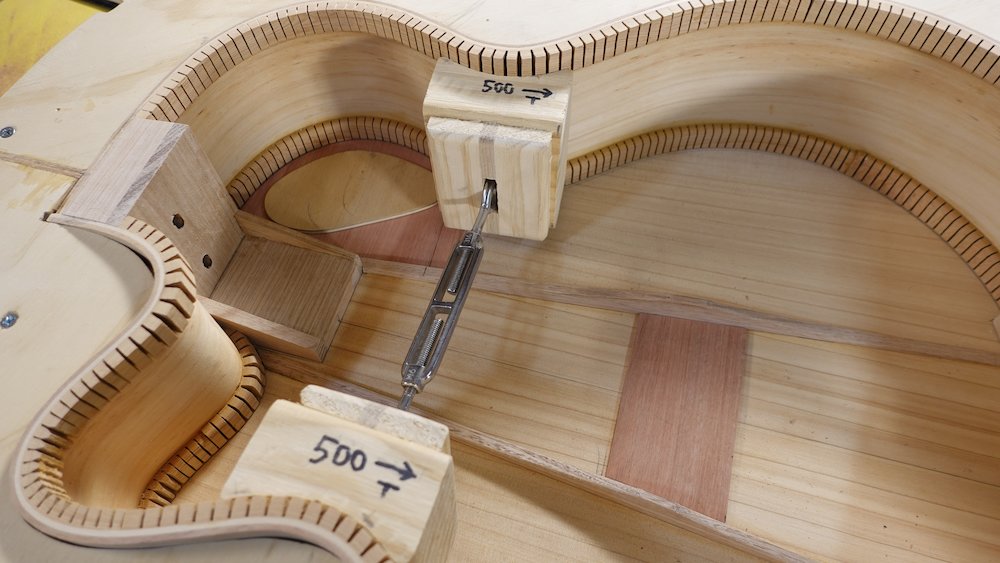
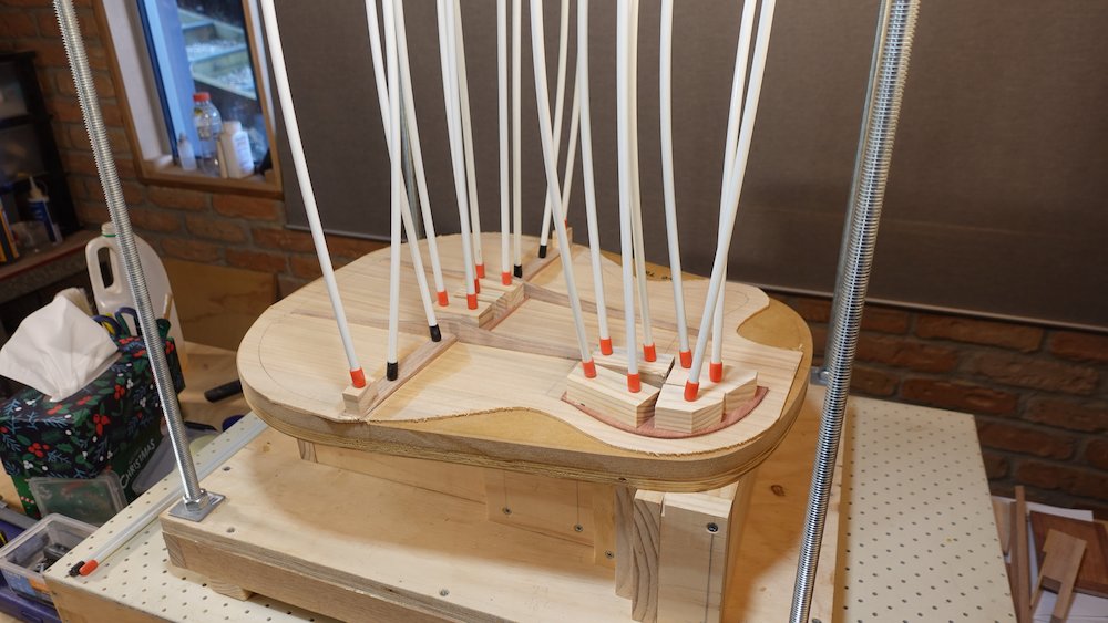
Fitting back and soundboard to sides
Overview:
Fit sides into solera mould with turnbuckle clamps if required
Mark positions of back braces on sides
Mark positions of soundboard wing braces on sides
Fill kerfs around those marks with shavings and polyurethane glue so they can be cut safely
Cut channels in sides for the back bracing and soundboard wing brace pieces
Attach final two centre strip pieces to back
Fit vertical side brace pieces aligning with back brace channels
Cut and fit support backing for pickup socket
Cut and fit support backing for neck strap button
Glue back to sides
Final check of bolt-on neck support tray
Glue soundboard to sides
Trim overhang with flush cut router bit
Trace, cut and smooth sound hole
Preparing to fit back and soundboard to sides
NB: fit sides into solera mould, it makes subtle differences to where we need to cut channels for the braces
Place access port cover in the hole (to support clamping)
will need to drill tail strap-button hole if not done already so that cover can be pulled out afterwards
put temporary 1/8" bolt & nut, protruding outwards as "puller"
Sides are in mould, turn-buckle clamps if required so no gaps
While "rolling" the back over the sides, mark where the braces meet the sides
Before cutting, fill in the kerfs around the marked positions with pine shavings and polyurethane glue
Try to have the filling just go down 5mm, so that the kerfs will look natural through the sound hole,
The idea is that the kerfs stop just before the bit that is to be cut away
This will prevent linings from crumbling when cutting channels
For the soundboard: same deal
Mark channels for wing braces
Fill the kerfs around them with shavings and glue
Now it is time to start cutting the channels
Start at one end, making sure both ends are centred
One brace at a time
Double-check position and alignment at every step
Cut brace channels too narrow, then check, then widen
Sand out incorrect pencil marks to avoid confusion
Cut small channels using small pull-saw, chisel and file
With the pull-saw, make two edge cuts,
make them too narrow at first - better to file outwards than have gaps
then two shallow wedge cuts to meet them,
then cross-hatch cut "hill" in between
finally use file and/or chisel to create the "downward" ramps into the body
check position at each step
Adjust so that back can curve over sides, into place
NB: finish centre-strips at this stage:
Trace neck block and access port edges onto inside of back
cut the final two centre strips to fit, glue them in and confirm that everything still fits
Filling kerfs with shavings and glue |
Filled kerfs after cleaning up |
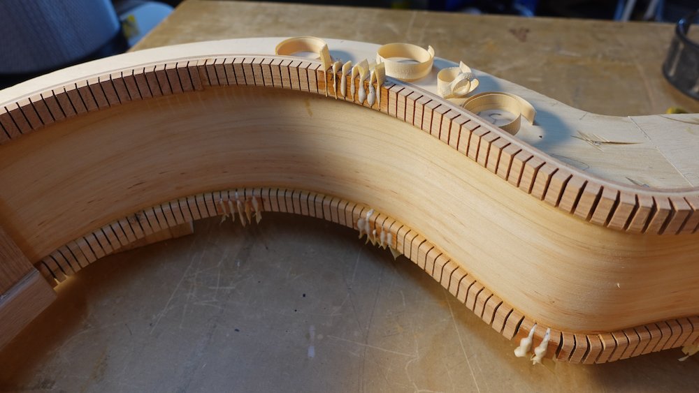
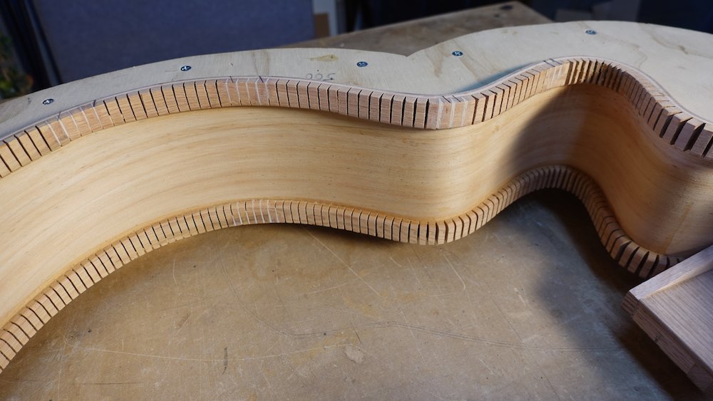
Cutting channels in sides for back braces |
Gluing outer two centre strips |
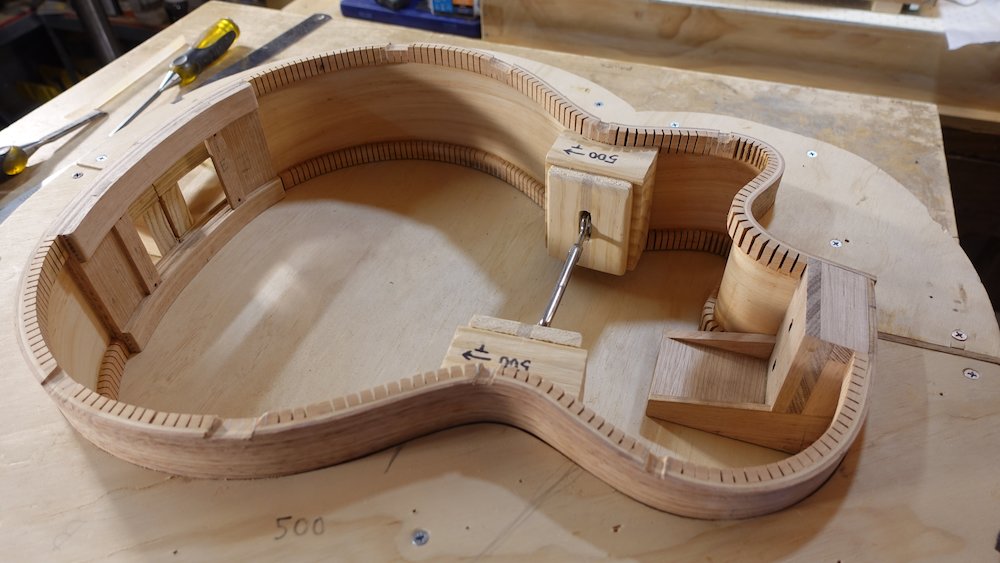
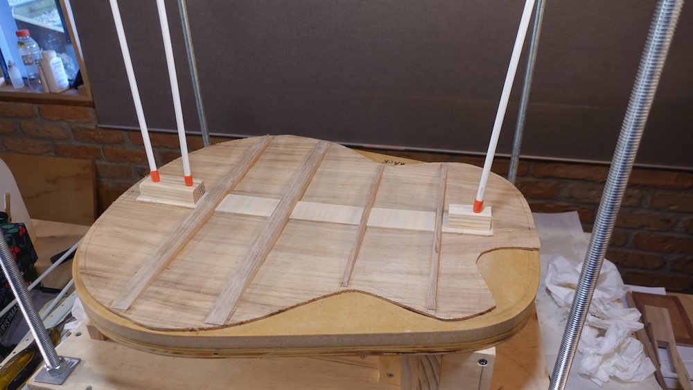
Cut and fit vertical side braces
Takes sides out of frame for easier clamping
rip some hardwood 8x5mm
Same positions as back braces (slots in kerfed lining)
Cut to fit between kerfed linings
15mm taper to 2mm top and bottom
(dimensions not critical)
Cutting channels in sides for soundboard braces |
Gluing vertical braces |
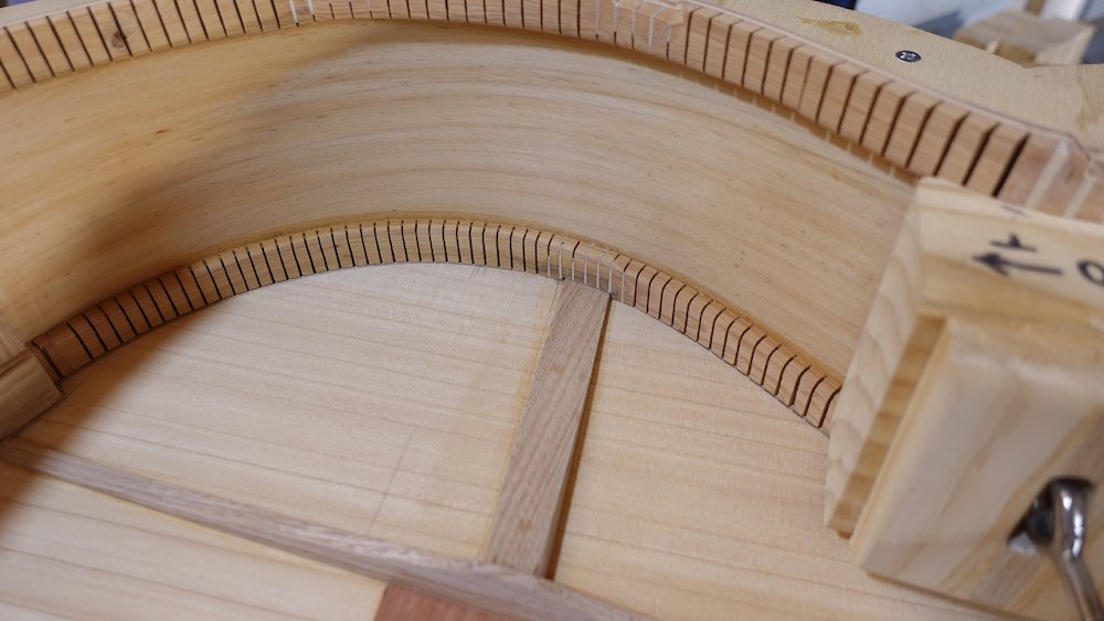
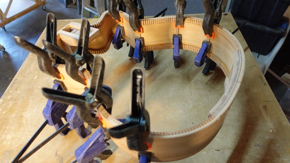
Cut and fit support backing for pickup socket
use some spare curved hardwood stock (leftovers from access port?)
Approximate length (see "Drilling for the socket", below)
Model |
Length |
Bass |
120 |
GP |
100 |
Parlour |
85 |
Cut and fit support backing for neck strap button
Cut a piece of hardwood about 55x55x10mm
Cut or sand to match curve "above" neck block
Nestle between curfed lining, and against neck block
Socket and strap-button supports cut |
Gluing socket and strap-button supports |
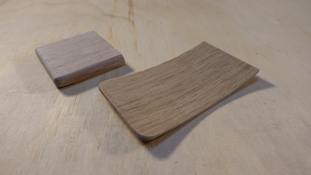

Socket support |
Strap button support |
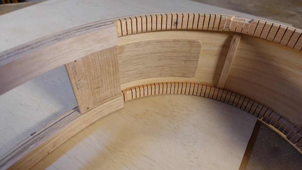
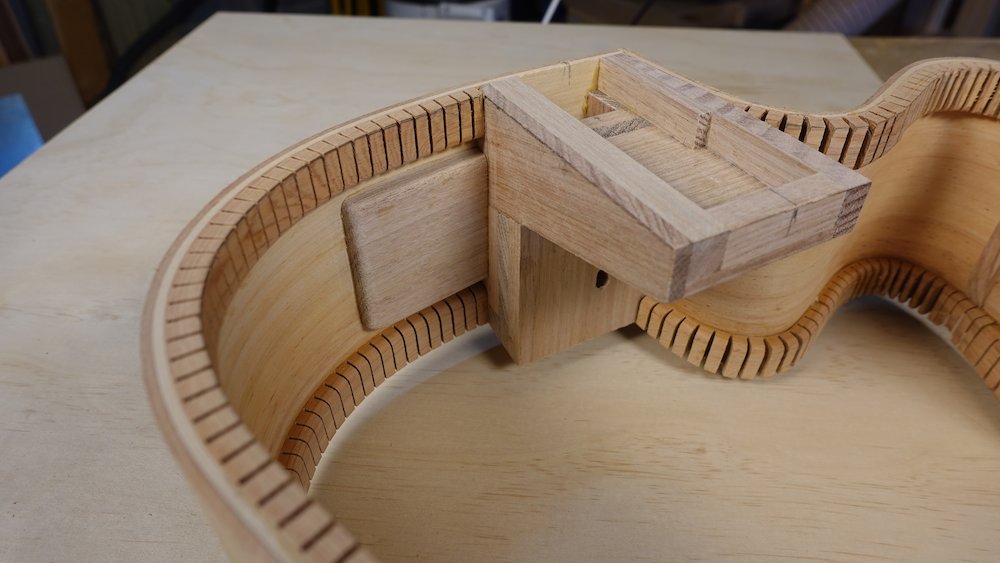
Glue back to sides
Back in frame with turnbuckles if required
If neck block is not perfectly square to centreline, consider attaching a "rudder" (see image below)
Go-bar deck & rods with split-cushion cauls to distribute force
(avoid uneven joins, gaps)
Do a full dry clamp-up first, to check that all join-lines are tight.
Starting to glue the back, note rudder to align neck-block |
Clamping the back using Go-bar deck |
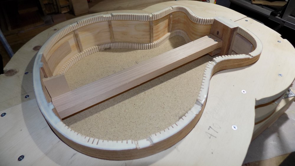
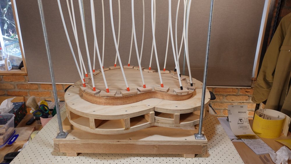
Glue soundboard to sides
NB: make sure the sides are square, so that the guitar can sit stable on its sides
Use wedged sticks if required,
to push top part of sides against mould
can't have turnbuckle clamps in mould when gluing top! (or can we? possible if exit stragetgy has been confirmed in advance!
less force will be required, as final shape is fixed by glued-in bottom
we're only "tilting" the sides to their final shape at top
Go-bar deck & rods with split-cushion cauls to distribute force
Another thing to consider:
since the guitar is resting on its curved back, excessive force
when fitting soundboard may cause the sides to warp slightlyconsider supporting the sides (with pieces of varying thickness)
Bolt-on neck experiment
check longitudinal alignment of fingerboard support tray and tongue
shim / pad / infill as required
Trim overhang carefully with flush-bearing router
**Climb-cut everything that's "flat"***
**For the rest, always go "downhill" (towards centreline)
Tear-out is a risk, especially if the bit is dull
(though small tear-outs will be covered by binding)
Make multiple 2mm climb-cut passes
Don't worry about 1-2mm overhang on back, due to curved back
it will be taken care of when cutting binding channels
... actually, when we level any side-waviness, we'll need to sand it back in those areas
Gluing the soundboard to the body |
Trimming overhang with flush-cut router bit |
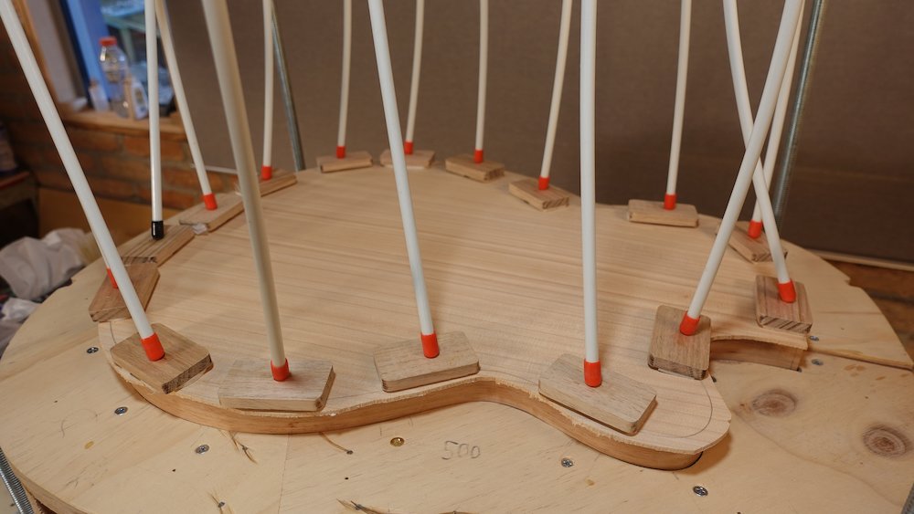
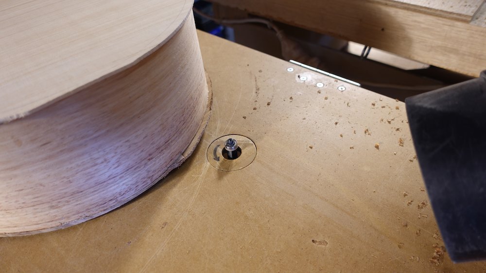
Trace, cut and smooth sound hole
Trace outline using template as a guide
Positioning
outside of hole follows 25mm inside upper bout edge
inside of hole approaches fretboard by about 25mm (more for bass)
inside of hole forms a smooth curve with lower bout (below the waist)
that curve involves a slight angle between the straight sections of each side (hole, bout)
template may not be 100% accurate to achieve this
(Originally used Dremel with downmill)
Large diameter Forstner bit for initial hole, then small router, then Dremel with mini drum sander
then finish with sandpaper wrapped around PVC pipes of various diameters
Very slight roundover around the hole - large roundovers are harder to French polish
For softer soundboards (especially Huon Pine)
Fit a soundboard protector for much of the rest of the build. It is so easy to scratch and dent!
Body fully enclosed for the first time |
Sound hole cut and sanded |
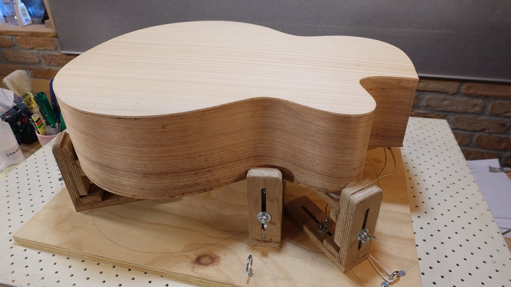
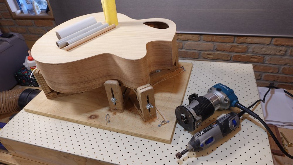
Bindings
Overview:
Pre-binding channel checks:
fix any side waviness
level access port cover
seal bindings are with shellac
square up neck-join area
Cut bindings channels
Cut vertical channel along the cutaway-neck corner
Expose neck-tongue pocket and neck support pocket (if bolt-on neck option)
Glue in vertical boundary strip
Attach bindings
Scrape bindings flush
Fill any major voids
From now on
Guitar body needs to rest on a towel to prevent scratches and dents
Before routing the binding channels
Check the sides for any waviness, and level them by aggressive sanding and scraping.
If not done so already, level access port cover at this time too
Make sure the area where the neck will be attached is square to the body centre line
Seal a strip 25mm each side of the bindings edges with shellac (for glued-on neck: except heel-join area)
This is to prevent glue squeezeout from soaking in, which is otherwise discovered when French polishing, and has to be aggressively sanded backFor bolt-on neck option, seal a larger area - the only think we need to keep clear of is the bridge!
Doing these steps after attaching the bindings risks having to scrape or sand the bindings too far back, leaving uneven thickness.
Rout binding channels
Sharpen router bit first!
Rout to 3mm inward depth, 8mm downward depth
Use router with vertial sliding jig and rabbet bit w. bearing
NB: take care at the neck/cutaway corner - do not round it over! Keep it square!
NB: also, make absolutely sure the guitar body is straight and secured in the cradle, so the channels are perfectly vertical!
NB: also, check that the router is cutting channels to the full (sideways) depth - make sure the sides are against the roller bearing, and measure depth to confirm 3mm all around
Direction of cuts
Any cuts along slopes - cut "downwards", (ie, towards waist, towards centre)
Any other cuts - climb-cut
After everything is done, go around again in the regular push-cut direction to tidy things up
Tips for building jig
Similar to StewMac vertical sliding jig
use two drawer runners, wheels aligned back-to-front
the assembly turned out a bit heaver (hello over-engineering!), so I use bungy cords to make it easier to use
for the "donut" to allow the jig to "ride" the sloping back edges, I used multiple layers of Perspex expoxied together
Router jig for cutting binding channels |
Closeup of bindings router jig |
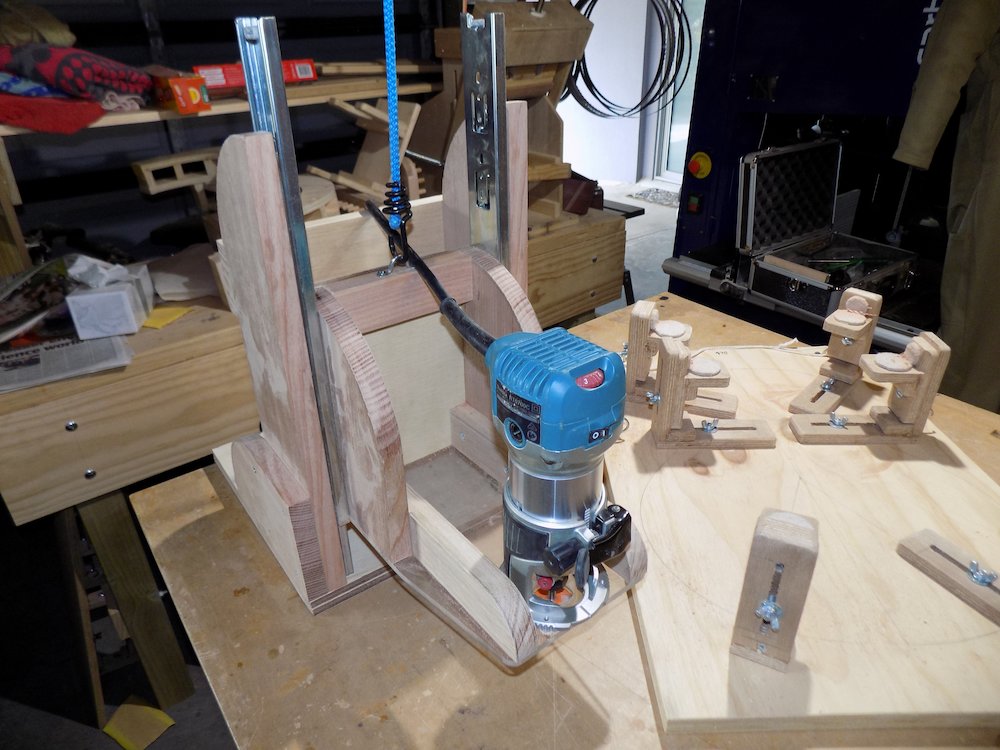
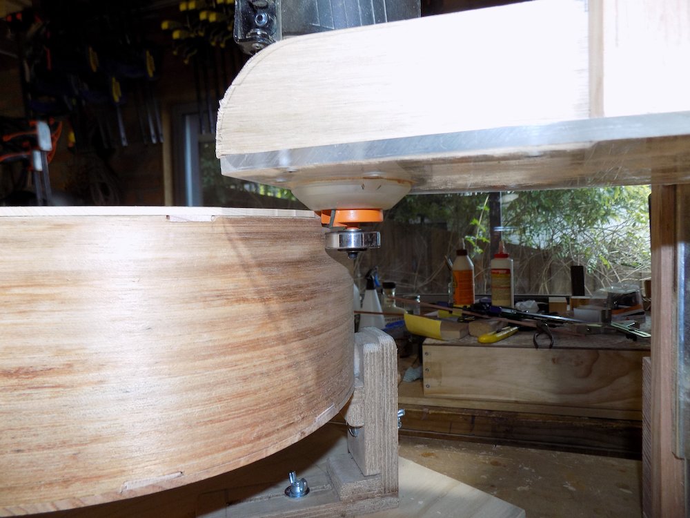
Rout (or cut with table saw) a vertical channel along the cutaway-neck "corner"
This can be done before cutting the binding channels, however the gap must be temporarily filled!
Doing it now raises no problem cutting the binding channels around the heel, but tear-out is more of a problem!
Temporarily glue in a piece of sacrificial scap to shore up against tear-outDecide on design:
Wider strip (show face at side, preferred) = best "enclosed" by bindings
Narrower strip (not preferred = bindings can butt up against it, in which case defer until after attaching bindings)2*2mm isOK but 8x3mm will better match the bindings
Do not exceed 3mm "thick" - the channel depth must not extend beyond the binding channel!
Make a strip to fill this channel, we will glue it in revealing the neck-tongue pocket
Use same wood as for bindings
Binding channels cut |
Slot for vertical neck-body boundary strip |
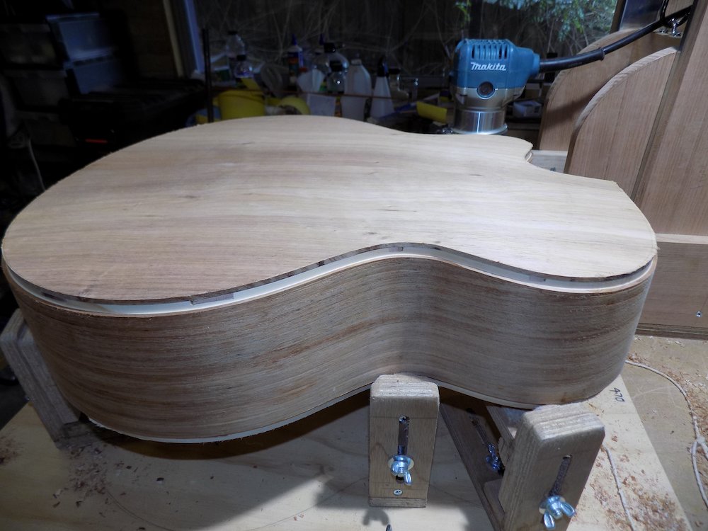
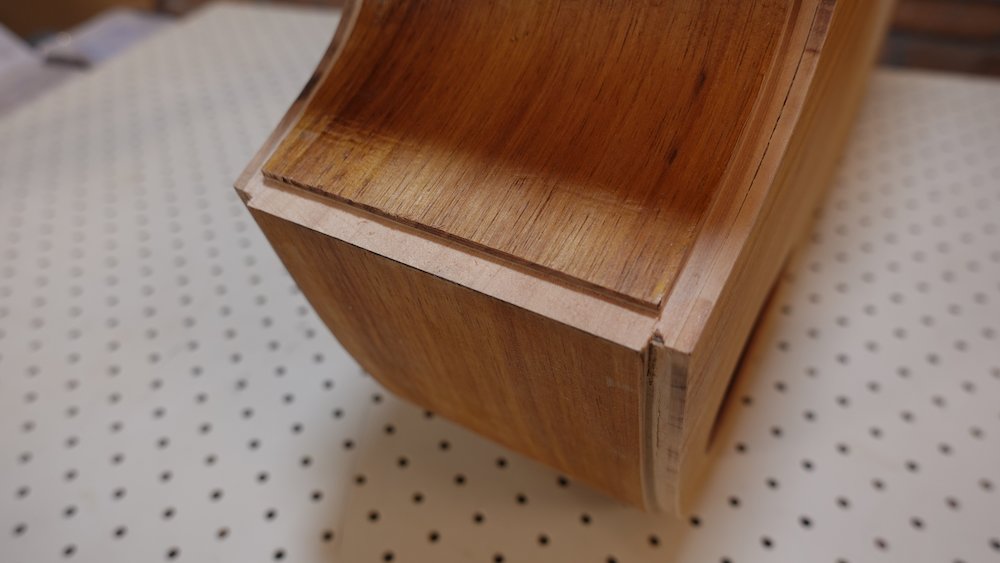
Expose neck-tongue pocket and fingerboard support pocket
This must be done after the binding channels are cut, or there will be problems near the heel cap!
Open up a hole in edge with pull-saw
Use flush-cut router bit
Square out and tidy up and with pull-saw, chisels and sandpaper
Glue in the vertical boundary strip along the cutaway-neck "corner"
(Strip and channel may have been cut two steps earlier, otherwise do it now, with anti-tearout measures)
Scrape and sand flush (neck-facing side)
Leave a bit proud on the side-of-body side (so that we can scape/sand flush after attaching the neck)
trim each end flush with the binding channels
Neck tongue and fingerboard support pockets exposed |
Gluing the vertical neck-body boundary strip |
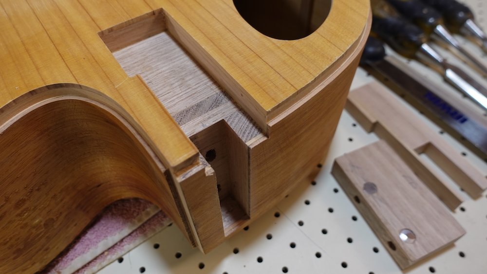
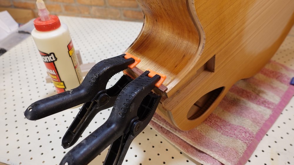
Attaching bindings
There is a problem with wooden bindings on a curved-back guitar, and managing it is a work in progress.
Since my design has an accent layer with two types of timber, imperfections are serious, as they cause
the accent layer to visibly wander towards the edge.
Principles to solve this problem
thinner inner layers conform more easily,
use a bending iron on the thick outer layer, so that if perfectly conforms to its intended shape at rest.
make sure curved back profile is smooth, with no "sharp" bends
most recent iteration:
side height follows a circular profile along linear body dimension (rather than a spherical back profile).
the trade-off is a slightly flatter area around the waist, where the sides move closer to the centre.
choose less-deep bindings, eg 8mm instead of 9mm
channels need to be perfectly vertical: guitar must be secure in cradle when cutting bindings channels so it doesn't tilt over
file/sand tilt-bevels (aka fillets) on inside surface at waist, upper bout, horn and cutaway so tilted binding presents a vertical face to glue
sandpaper and scaper seem to be the best way to do thisdo at least one dry tape-up to test that tilt-bevels are adequate before gluing
Bindings tilt |
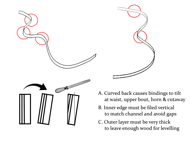
My design uses two different timbers to give a "purfling-like" appearance.
Soundboard side
Lighter-coloured soundboard favours a three-layer plan (dark/light/dark)
No curvature means far less risk of gaps around waist & cutaway
Inner layer: dark, 0.6mm
Middle layer: light: 0.6mm
Outer layer: dark, 1.8mm
Rounded back
Darker-coloured back makes a two-layer plan (light/dark) more attractive
Curvature means we need to file/sand in some tilt bevels at the waist, upper bout, horn and cutaway
However, if the inner layer is thick enough for those bevels, any gaps will mean we need to pare back the correspondingly-thinner outer layer, not only making the problem very obvious, but also raising the risk of sanding through the outer layer!
Current working notes...
Inner layer: light, 0.8mm
Middle layer: dark, 0.6mm
Outer layer: dark, 1.6mm
Important: to reduce tilting of bindings due to curved back
sand away 0.25mm-1mm tilt bevels of lower-inner corners of bindings
at waist
at upper bout (non-cutaway side)
at cutaway outer curve ("horn")
at cutaway inner curve
Note that although the bevels initially have a curved border, I then attempt to sand the inner surface completely flat.
Fine-tuning tilt-bevels
It is essential to perform dry tape-ups to ensure there are no gaps.
Clamping method, traditional option
Titebond
four stages
cradle body in half of the solera jig
use elastic clamping jig (aka B&D vice)
Clamping method, if dry tape-up is perfect
cut bindings to correct length at tail
a minimal bead of Titebond in the channel to attempt to seal it from excessive CA soak-through
redo tape-up
apply CA glue, enough that it soaks between all layers, but not much further
four stages is best, non-cutaway first, then trim the neck-block overhang and do the cutaway side
if glue seeps underneath tape, consider replacing each piece of tape after applying glue
NB: note that in one of the images below, I have used the clamping jig backwards.
This is OK for a small-bodied guitar, but ideally the jig should be the right way round, as shown in the first image.
Original method: bindings clamping vise |
Clamping the bindings with elastic in the vise |
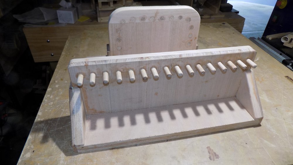
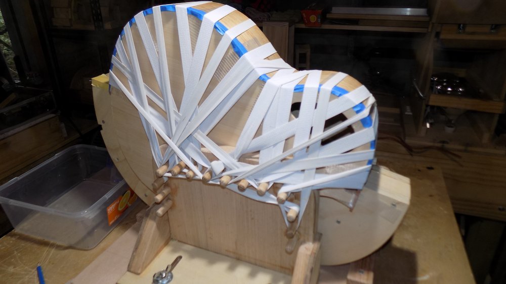
Optional method: Titebond and CA |
Filing (sanding, scraping) tilt bevels for curved back |
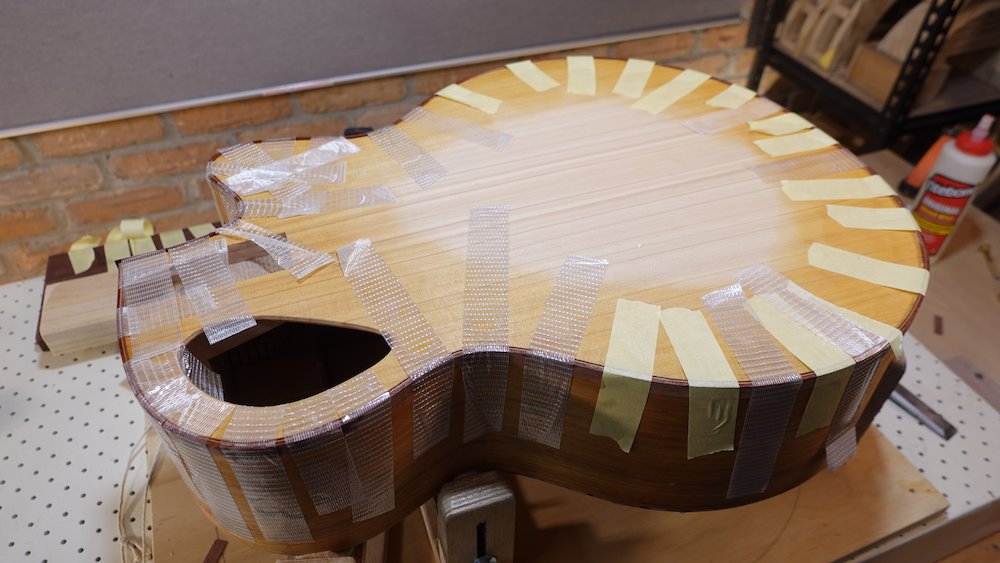
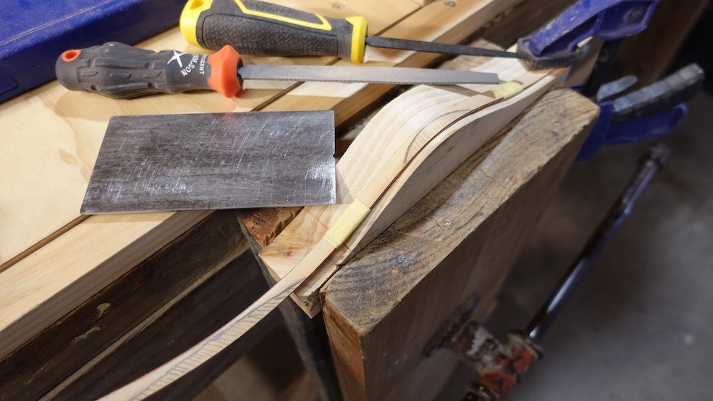
Tilt bevels marked out around the horn and cutaway |
After gluing both sides of the back |
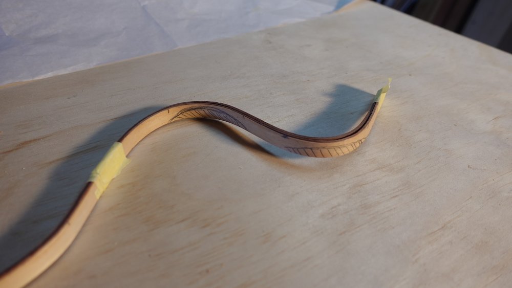
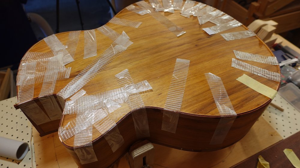
Scrape bindings flush
The more overhang, the more work!
For the soundboard and back
For the ends that extand up/down past the bottom and soundboard, using a spokeshave can remove material quickly
However, great care must be taken not to dig in, and because there are two layers of binding, this means that some sections cannot be trimmed this way.
The scraper is also susceptible to grain direction, but less seriously.
Spokeshave, then scraper, then sandpaper.
For the sides
Wrap the Shinto saw-rasp tip with two layers of masking tape
Hold it by the tip so we can use pull-strokes
The masking tape protects the sides from being scratched
Use this for coarse material removal
Scraping the Shinto longituninally along the bindings can weaken the timber, making subsequent filing/sanding easier
After the Shinto, sandpaper
After sandpaper, the scraper with a fresh burr!
Binding shaved, scraped and standed level |
Back view |
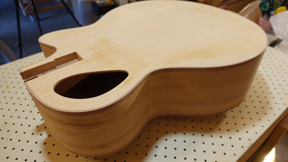
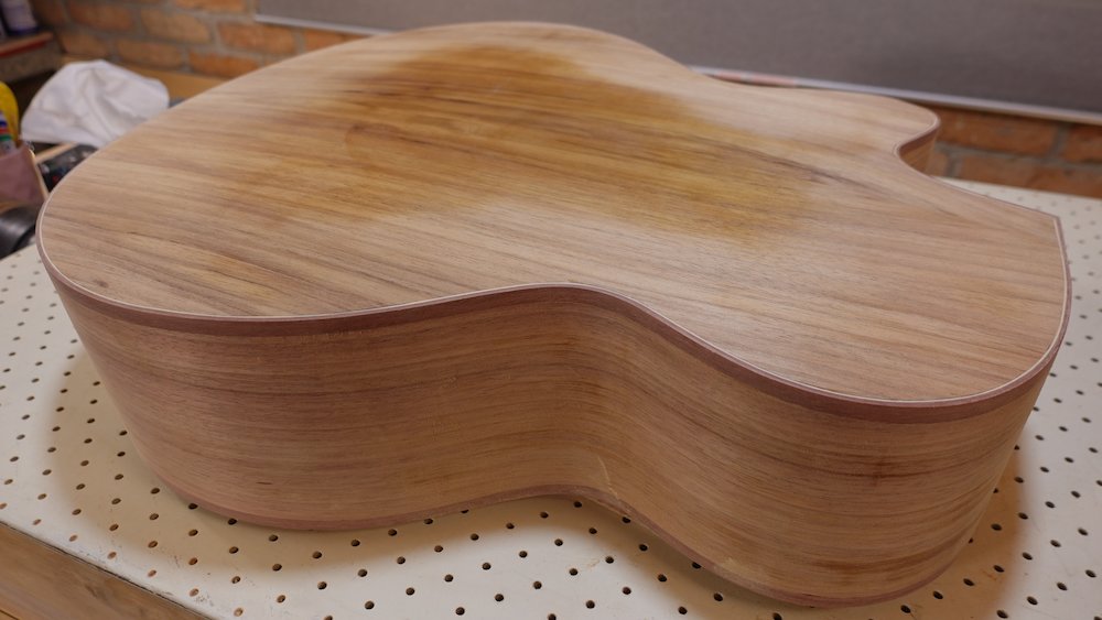
Shallac Test
Apply more shellac around the joins, this serves two purposes:
to reveal any glue that needs more sanding,
to reveal any scratches from the Shinto... that need more sanding
it is much better to do this now that after starting French polishing
If the bindings have an accent layer
File or cut a small notch at the heel-cutaway 90-degree join, where the accent layer buts onto the heel
This void can then be filled (matching dark bindings timber), giving a concentric or nested appearance
For glued-in neck option, clay-based filler such as Timbermate is adequare
For bolt-on neck option, a mixture of glue and sawdust is recommended, as it forms part of an exposed edge
See photos below
Bindings corner with notch filed |
Bindings corner with wood filler (later, after attaching heelcap) |
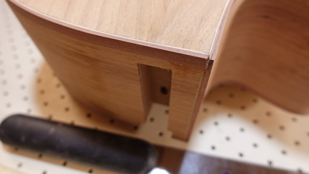
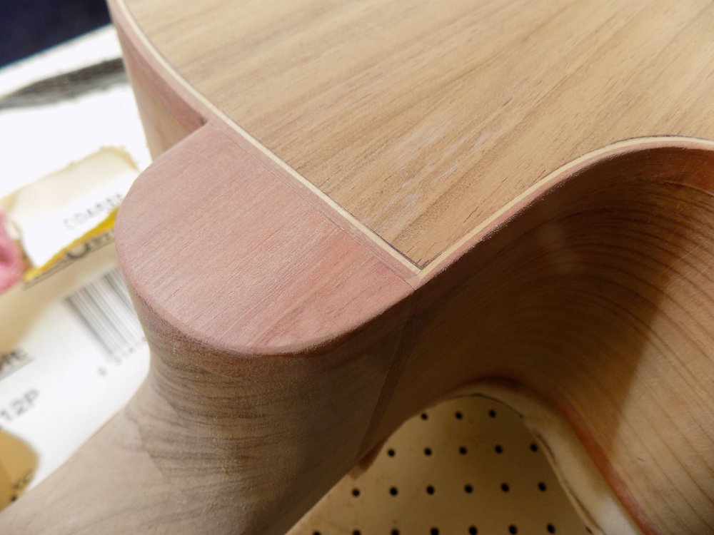
Fill any major voids in body
Ignore gaps smaller than those to be dealt with when grain-filling
Find them all
Glue and sawdust, or coloured hard-setting putty
Glue and sawdust is difficult to remove later...
Very annoying to keep finding one more when it's time for finishing
Sand adequately (important if using glue and sawdust, or shellac will reveal pale spots)
Fretboard
Overview:
Cut fret slots in fingerboard
Prepare fretboard bindings (optional)
Trim fingerboard to width (off-centre!)
Cut wave motif on end
Widen fret slots
Attach bindings (optional)
Inlay and side dots
Finalise neck and headstock carving
Index pins to align neck and fretboard
Finalise trimming of neck and fretboard (leaving a tiny bit extra at heel)
Drill tuner holes in headstock
Making a fret-position template for the StewMac jig
Create a table of fret-positions, as well as between-fret distances for double checking
StewMac website has a good calculator for this
Use custom jig to hold large (60mm) calipers and length of alumium bar
Slide calipers to fret positions, scribe line along jaw using compass point
Use second (normal size) pair of calipers to double check inter-fret distances to avoid "off-by-one" errors
Use bandsaw to cut slots, with sliding bevel and a piece of masking tape to line up the scribed lines
For some scale-lengths, the final few frets will have to be cut "from the other end"
Either re-scribe those lines using caliper jig, or carefully transfer using set square
When cutting "from other end", don't forget that the slots must be one the other side of the scribed line!
(Alternatively, a micro table saw with a thin carbide blade can do this more accurately)
Clean up slots with files / hacksaw blades / sandpaper wrapped around scraper (or other thin piece of metal)
When using, trim the zero-fret line 0.7mm shorter for better intonation
Bound-neck option
in my experience, fitting frets on a bound fretboard is more sensitive to too-narrow slots
it is highly recommended to widen the fret slots with material-removing method (not just stretching the fibres at the surface)
Jig for large calipers to make fret slotting template |
Scribing lines at fret positions |
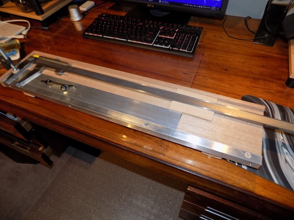
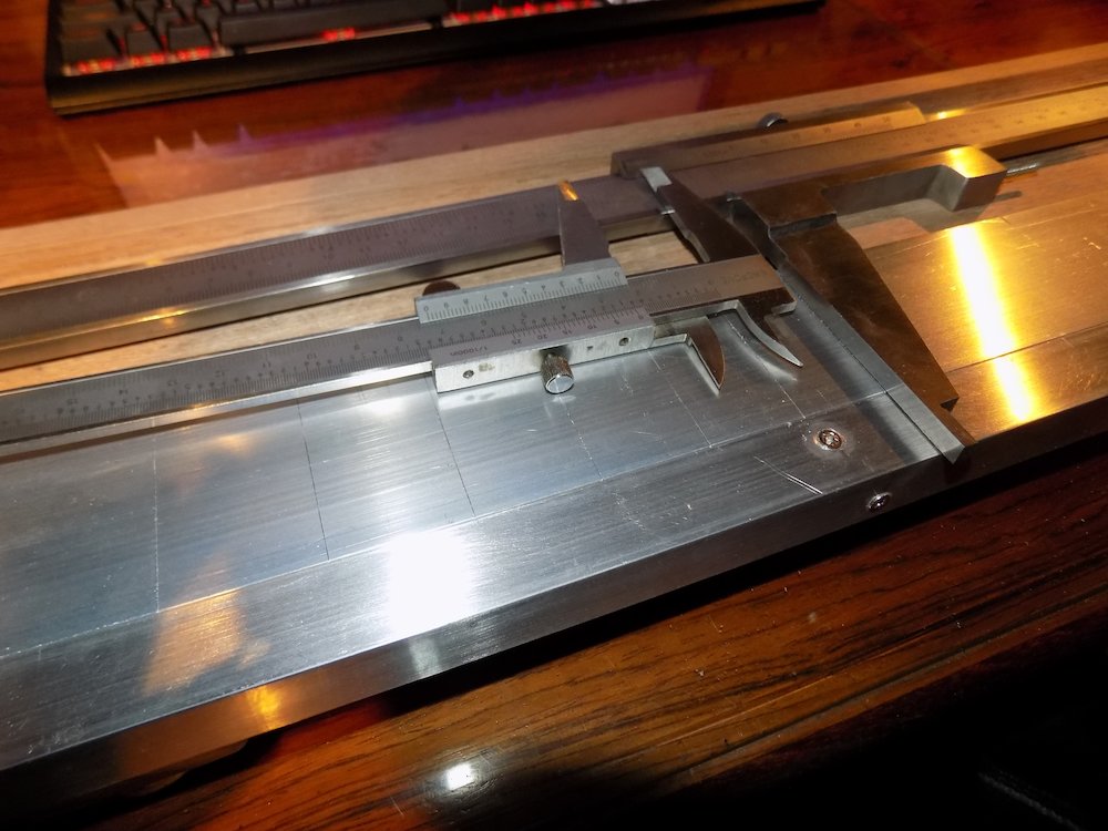
Cutting slots for the fret-slotting jig's index pin to fit into |
Completed fret-slotting template |
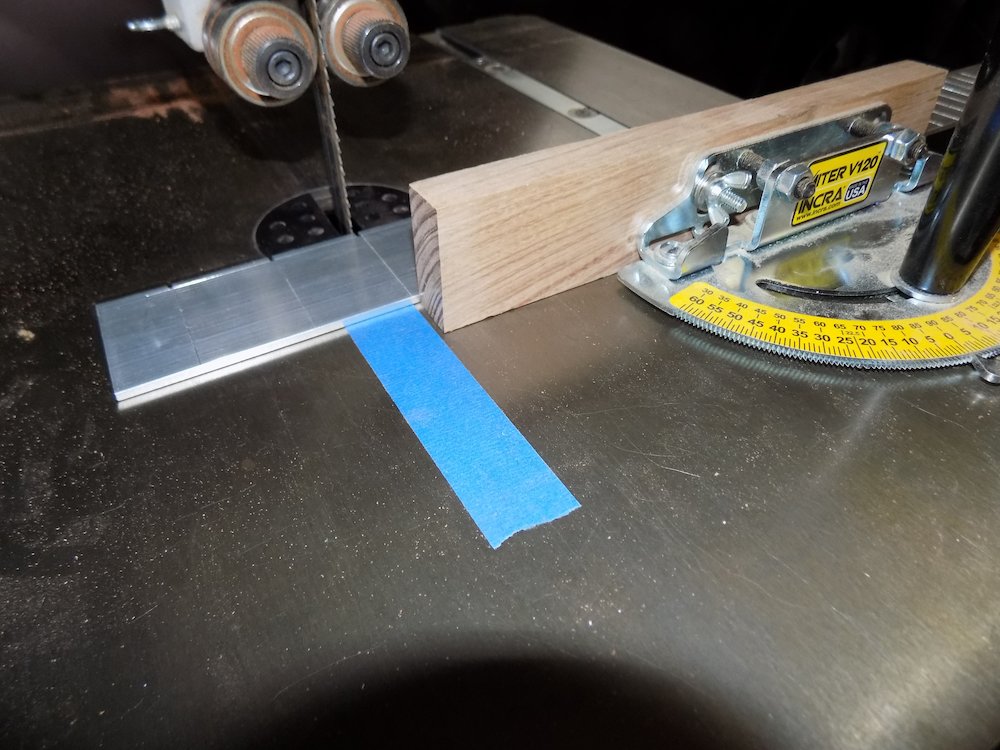
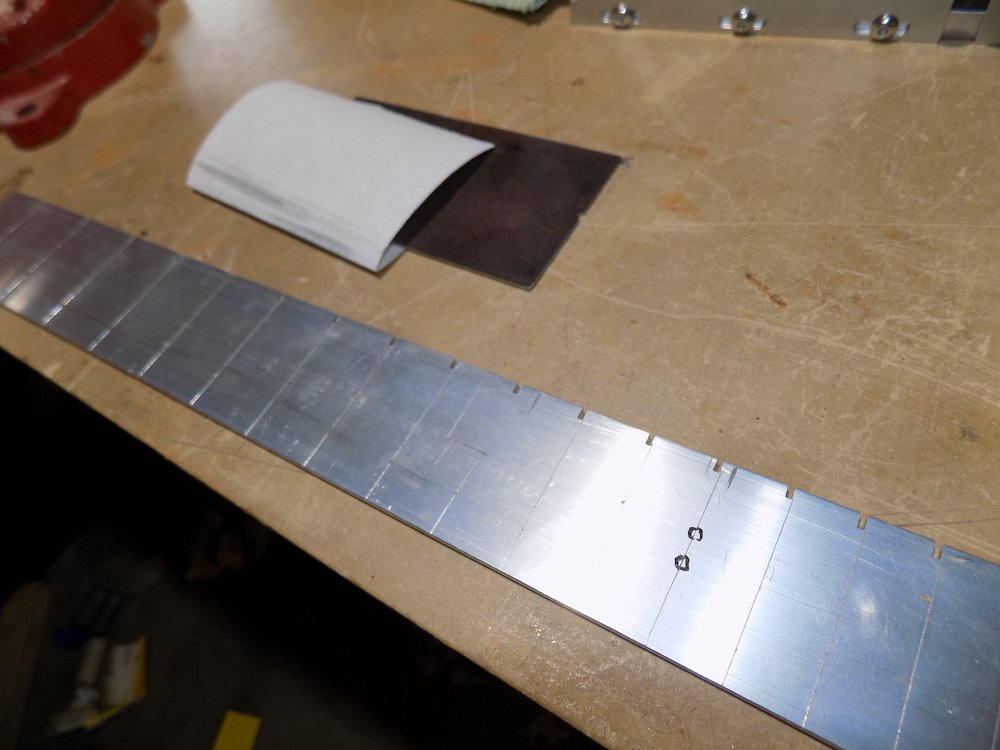
Plan fretboard fret count and width
Width extension ratios (of positions of fret pairs)
Model |
Fret plan |
Ratio |
Guitars |
21st/14th |
1.27 |
Basses |
19th/14th |
1.2 |
6-string / 14th-body-fret: 21 frets
width at nut: |
44 |
|
width at 14th fret: |
56 |
(nut+12) |
width at 21st fret: |
59.25 |
(nut+15.25, or 12 * 21st/14th ratio) |
12-string / 14th-body-fret: 21 frets
width at nut: |
48 |
|
width at 14th fret: |
61 |
(nut+13) |
width at 21st fret: |
64.5 |
(nut+16.5, or 13 * 21st/14th ratio) |
Bass / 14th-body-fret: 19 frets
width at nut: |
42 |
|
width at 14th fret: |
58 |
(nut+16) |
width at 19th fret: |
61.2 |
(nut+19.2, or 16 * 19th/14th ratio) |
length if fretless: |
612 |
Blank lengths
Bass |
~700 |
Guitars |
~600 |
Slotting fingerboards for frets
Use jig & template
Setting up the height of the saw guide |
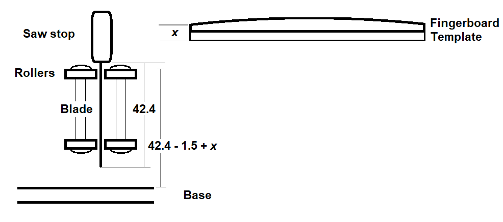
(48mm is typical)
Check depth after slotting 0th fret (doesn't matter if it's not right, we're going to cut all the way through on that one)
Cutting fret slots |
All fret slots cut |
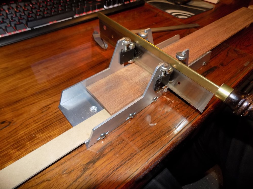
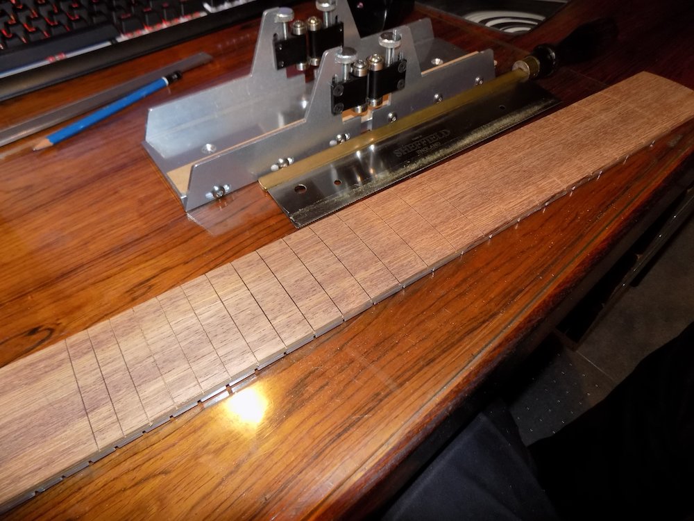
Bound fretboard option
If doing this for bolt-on neck option, recommend "understated binding":
same timber as fretboard,
no inner accent layer,
no binding around wave motif at end,
only benefit is tidier fret-ends.
Reason: binding has no glued support from below
Less forgiving if freboard width needs to be adjusted after finalising neck fit
Wave motif at fretboard end tricky to bind/clamp
Suggest milling some Jarrah 3mm thick, or Jarrah 2.3 and Celery-top 0.7
Bend some lengths to match wave motif on bending iron
Trim fretboard width 4mm thinner (and length 2mm shorter if binding wave motif end)
Trim fingerboard to width
Consider
offset the sides so the highest part of the curve is slightly toward the treble string
this will allow the treble string saddle notches to sit a little higher
3mm MDF strip, double-sided sticky tape, bandsaw fence
use 3mm MDF strip, slightly wider than fingerboard
attach fingerboard to strip with double-sided tape
rotate so that cut-line is parallel to one side, slightly "in" from edge
setup bandsaw with fine blade
use bandsaw fence strips slides along
MDF sacrificial backing also prevents tear-out
repeat for other edge
Finish both edges using aluminium straight-edge bar
and double-sided tape-attached sandpaper
Finalise wave motif on fretboard
Freehand draw, rough cut with bandsaw,
progress with belt sander,
finish tight radius with sandpaper wrapped around PVC pipe
Fretboard mounted "askew" on backing MDF board for trimming. |
Cutting one side of the fretboard to width |
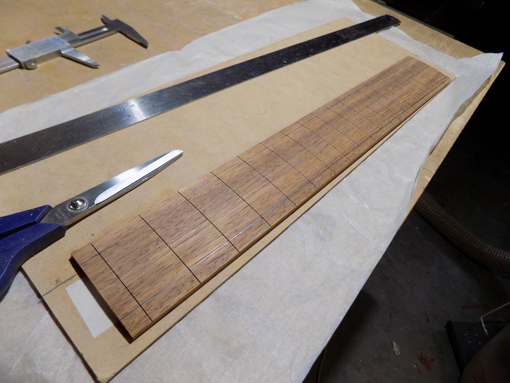
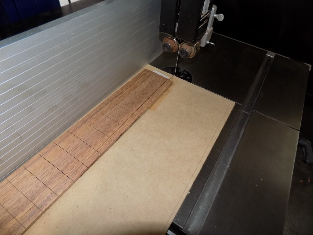
Cutting the other side (after re-positioning with double-sided tape) |
Fretboard trimmed, sanded to final width, and with wave-motif cut |
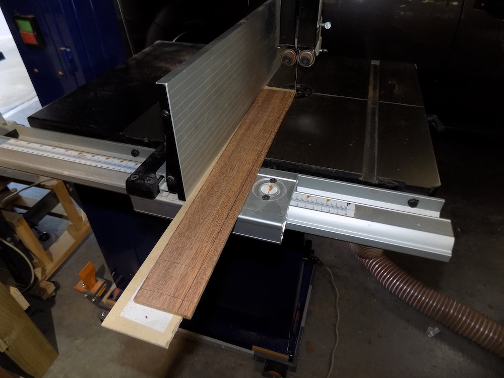
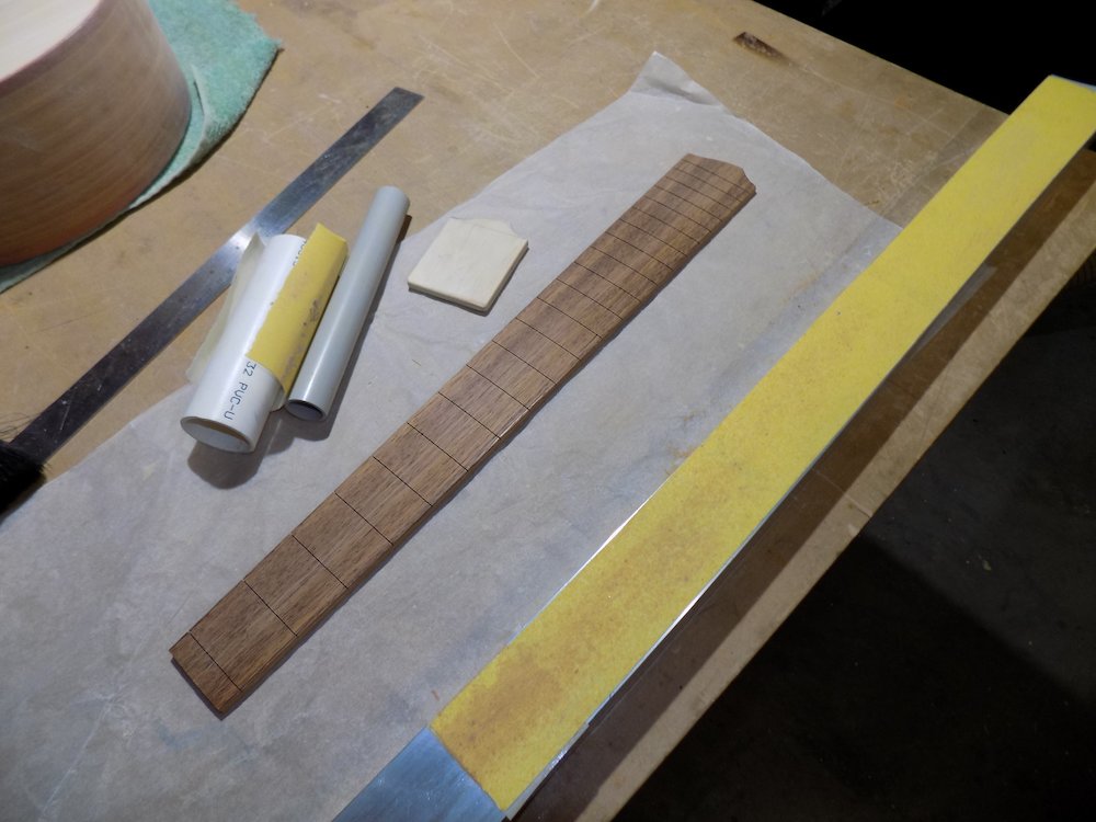
Widen all fret slots
Very important for bound-neck option
Quite easily done now
This will reduce the amount of hammering, especially onto an unsupported area of the fretboard
Start by scoring with a compass point
Finish by tapping in a piece of fret wire with the barbs removed
(Alternative: using a fret press in the drill press)
Attach fretboard binding (optional)
Challenging bending and mitre-work around wave motif!
Use thicker-than-required binding at sides, and thinner around wave-motif for easier bending
Next time: cut a rabbet under very end of fretboard, glue in an extension
...Binding around wave-motif will therefore more accurately be purfling
Clamping fingerboard binding |
Bound fretboard (understated option for bolt-on neck) |
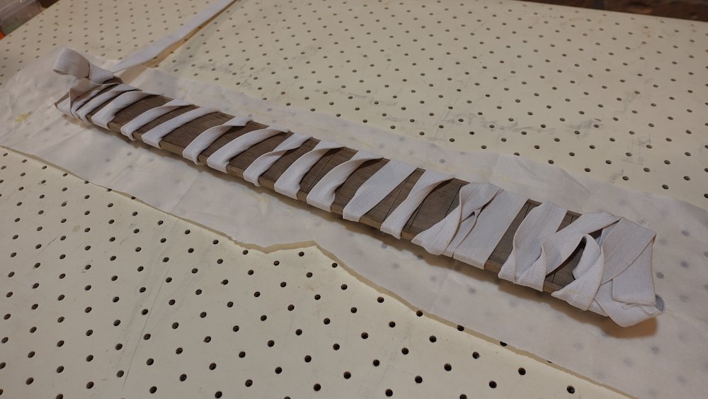
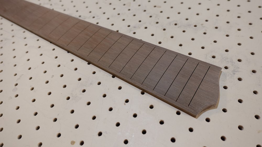
Binding around wave-motif glued in |
Bound fretboard completed (width to be finalised) |
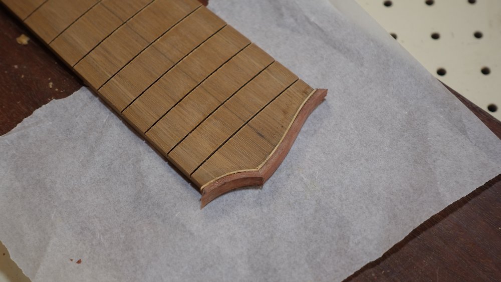
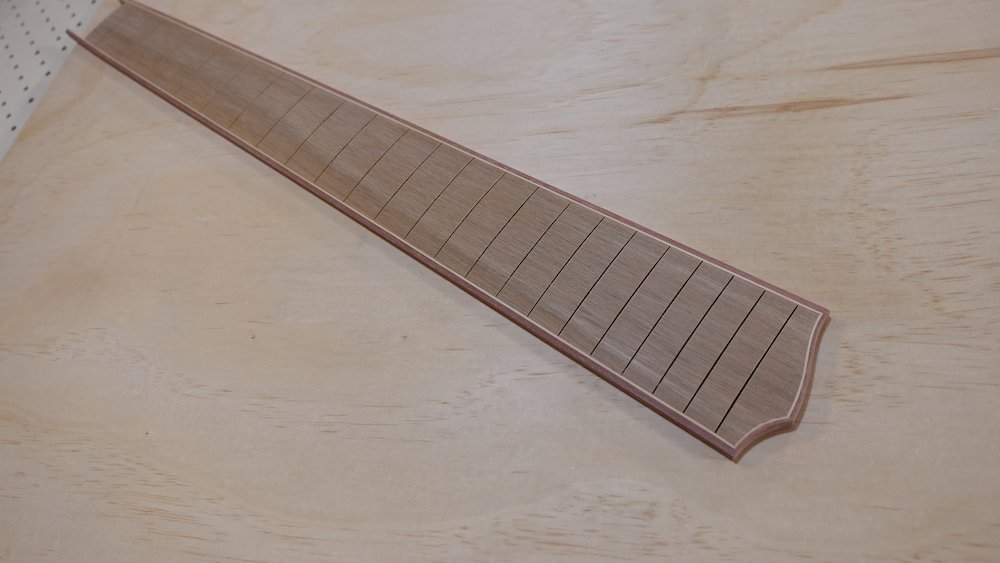
Fretboard inlay and side dots
Drizzle super-thin CA to fix
Inlay dots
Forstner bit (using stop-nuts on the drill press to get accurate depths)
To drill the 12th-fret pair without resetting the stop-nuts, shim the edge with a ruler, and don't quite bottom out.
NB: if following the saddle-balance, offset-fretboard option, take note that each side will be a different thickness
12th-fret pair: edge 5-8mm from fretboard edge, therefore centre is 9-12mm from edge
If the fretboard is not bound:
Having them not quite perfectly centred is OK
Leaving a bit more spare width at the bottom edge
Which we may need to remove when levelling the cutaway-heel joinIf the fretboard is bound:
Much less wiggle room!
a little CA on top is OK
having to sand them flat is also OK (400)
if hole too deep, shim with little circles of paper - though this can make them sit unsteady
a little sawdust in the holes might be a good idea
Side dots
Dremel drill press with 2mm drill bit and steel-and-aluminium side-dot jig
The top of the jog is painted black to more easily see marks through the drill-bit hole
NB: if following the saddle-balance, offset-fretboard option, the bass side of the fretboard will be thinner, and will thus require shimming.
This is because it places the hold a fixed distance from the underside of the fretboard
A piece of cardboard, possibly tweaked with a layer of masking tape, will probably suffice.
Clamp fretboard to a piece of thick timber to keep the upright square, and the top horizontal
12th-fret pair: about 10-12mm spacing (4mm for fretless)
Holes drilled for fretboard inlay marker dots |
Fretboard dots flooded with CA glue |
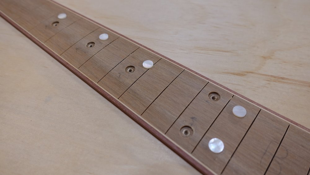
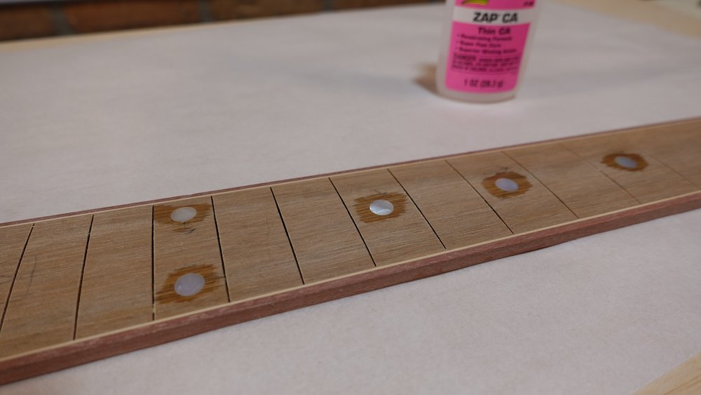
Fretboard dots sanded level |
Aluminium and steel side-dot jig (inside) |
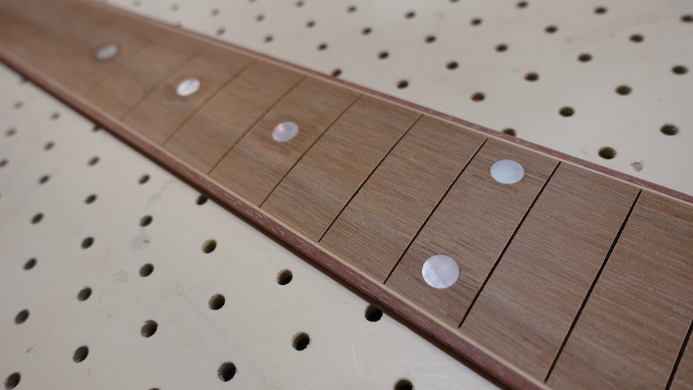
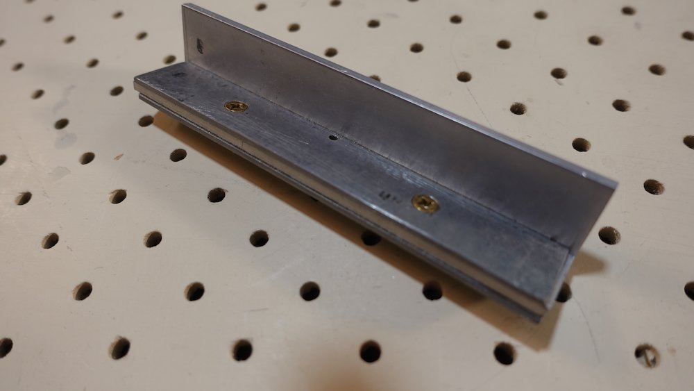
Drill press set up with jig |
Inserting side dots |
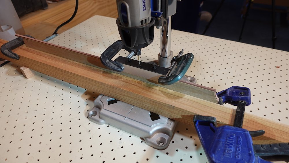
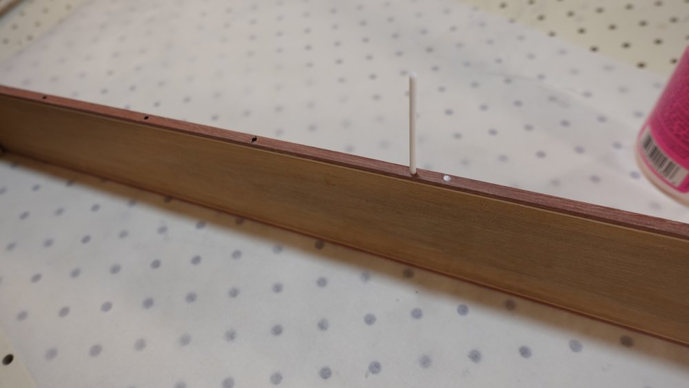
Side dots flooded with CA glue |
Fretboard side dots sanded level |
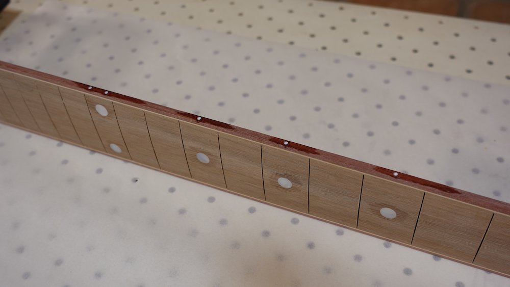
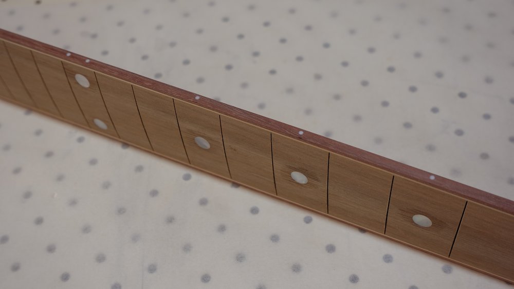
Finalise neck carving, now we have fingerboard to size
trace fingerboard onto top of neck
lots of fiddly work
scraper useful
coordinate neck width with body (but leave a little bit proud both sides if possible)
finalise headstock shape with spindle of belt sander
Make index pins for fretboard
cut the heads off two small nails, leaving 11mm and 15mm
nail them into top of neck, short one near nut, longer one near heel
leave 3mm sticking out
file those stumps to sharp points with a file
impale the fretboard over the indexing spikes, hammer/clamp if needed
Progress trimming neck to fit fretboard
concentrate on the top side
leave some material to be removed on the lower side (cutaway)
(This will make cutting the neck-tongue slot a bit easier)
Also finish the neck-headstock transition now that the fretboard is in place
Headstock carving completed |
Zeroing in on neck width (top side) |
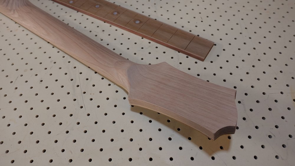
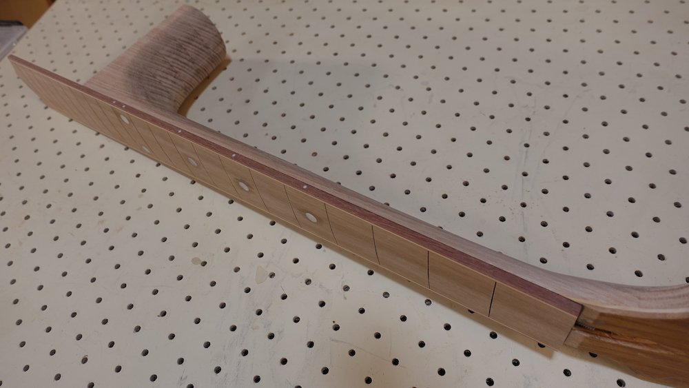
Drill tuner holes in headstock
My choice of tuners
6-String: |
Gotoh SG381-01C |
12-string: |
Wilkinson 3+3, SKU TU-141-010 |
Bass: |
Gotoh GB-707C |
clamp drilled headstock template to headstock
get a nail, wrap with masking tape if diameter not correct
poke through template holes to make marks in headstock
Easy method
Drill holes with Forstner bit (against sacrificial base)
Recommended method
Set drill press stop nuts so that the Forstner bit spike just pokes through the back
The hole stops about 1mm before the other side
Turn piece around and finish from the back, using the hole the spike made to guide the bit
This give perfectly clean holes on both sides
Hole diameter
6-string |
10mm |
Bass |
14mm |
Index pins to repeatably locate fretboard |
Tuner holes drilled in headstock |
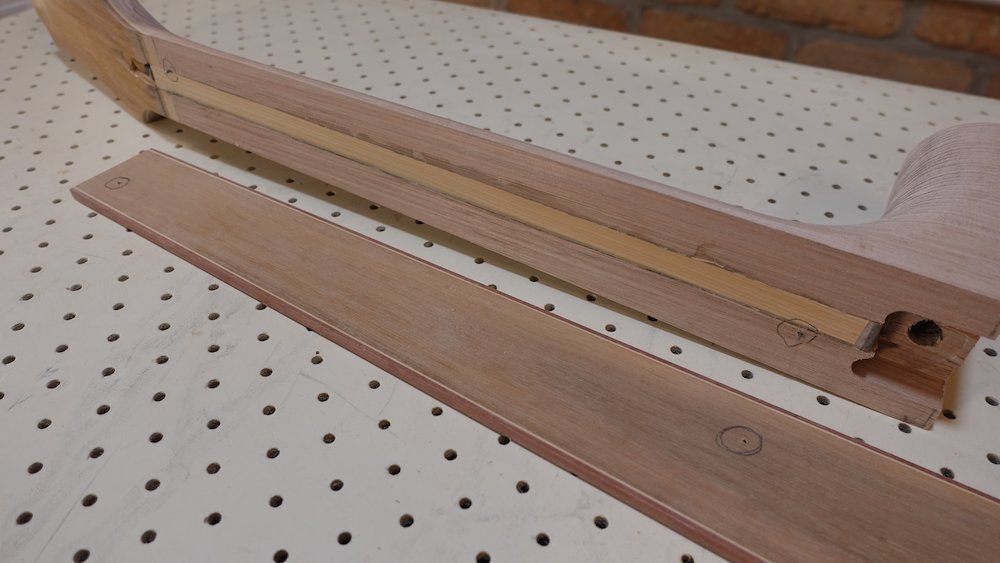
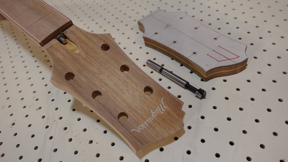
Fitting neck to body
Overview:
Plan bridge height and estimate neck angle
Cut neck angle with No. 8 jointing plane and shooting board
Cut neck tenon slot in heel (glue in protector block at fragile bottom)
Make any adjustments of neck angle that can be done at this stage
Cut heel for heel cap
Glue neck tenon into heel slot
Attach neck to body
Adjust neck angle if required
Level neck-cutaway transition
Temporarily attach fretboard and finalise neck/fretboard/body fit
Bolt-on neck option:
finalise fretboard support extension fit
level it perfectly to soundboard surround
plan bolt-hole position, drill
glue fretboard to neck
Finalise neck-cutaway transition
Ideal bridge height
For an acoustic guitar the bridge should be ~9mm
The saddle should extend about 4mm above this (in the middle), giving a total string height of 13mm (0.5")
The saddle slot should be at least 5mm deep, aiming for "two thirds of the saddle in the slot"
Opinion seems to be the neck angle should aim for a ruler along the frets having 0.5..1.6mm of clearance above the bridge (without saddle)
However, there are two complications:
For basses, action at the 12th is generally 1mm higher
For fretted instruments, we will be doing this before installing the frets
Therefore, taking an average fret height of 1.2 (from 149/152/47095/47104 fretwire):
Model |
Range |
Mid-target |
Incl. frets |
0.5..1.6 |
1.0mm |
Guitar, pre-frets |
-0.7..0.4 |
-0.2mm |
Bass, pre-frets |
-2.7..-1.6 |
-2.1mm |
Fretless bass |
-1.3..-0.4 |
-0.9mm* |
NB: these targets depend on the fretboard being perfectly flat along its entire length, including the section on the guitar body.
*Actual experience with fretless basses indicates that a 2mm undershoot is better
Assuming:
6mm fingerboard depth (pre-frets),
9mm bridge height,
projected neck-body line should stand off bridge position by 2.5mm
the the A-frame soundboard curvature delivers something pretty close to this with a perfectly straight neck-body transition
Estimate neck angle
Ideally, the heel face will be cut perfectly square. Check that it is
Ideally, the soundboard will have a slight curve due to the curved A-frame bracing
Ideally, the neck block will be perfectly perpendicular
Ideally, we want a perfectly straight line across the junction of the neck and soundboard
Although the curved soundboard will fall away from this line (allowing bridge height), the fingerboard should be able to be perfectly straight
Therefore, we will need to sand a slight angle into the heel face
Cutting neck angle (previous method)
Line up the neck with the body to get a rough estimate of the required angle
Sand almost that estimated angle into the heel face using band sander, the tidy it up with a strip of sandpaper attached to a board
This will also dress the face, which will be rough from being cut on the bandsaw
Take care not to crown it
Cutting neck angle (current method)
Make sure length of neck is almost right, so plane only has to change angle, not do serious shortening
Use a No. 8 handplane and custom shooting board with adjustable fence to get 90% there
A No. 7 could also be used, but will be too narrow for 5-string basses
The heel has a complex cavity for fingerboard support - this needs to be packed
The adjustable fence controls the longitudinal angle
Control lateral angle by raising or lowering the bridge against the fence, then clamp
Measure, don't calculate
Take the finest shavings possible, taking care to avoid end-grain tearing
Multiple passes may be required
If required, the final part of fitting can be done with the sanding board, "leaning into" the corner or end that needs most taken off
Preparing to pack heel cavity |
Heel cavity packed ready for planing |
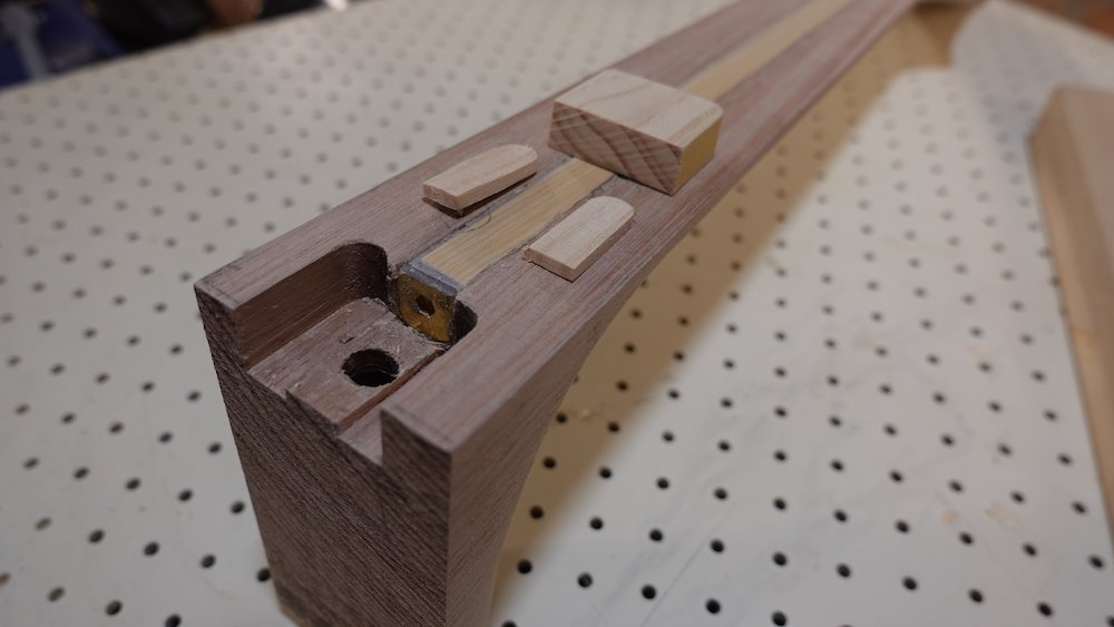
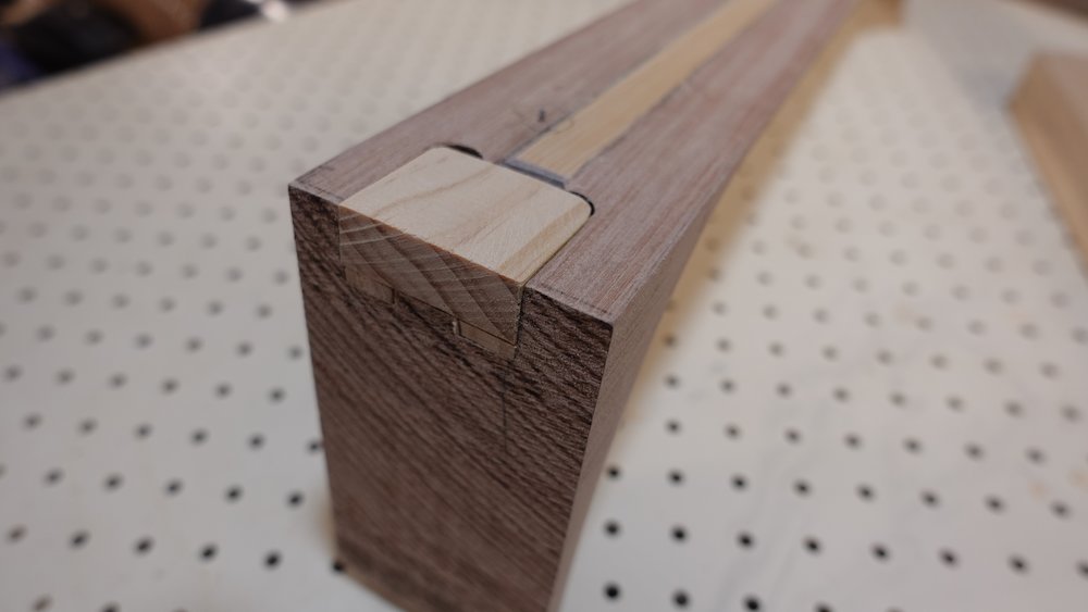
Neck clamped in shooting board |
Planed area "creeping across" heel face |
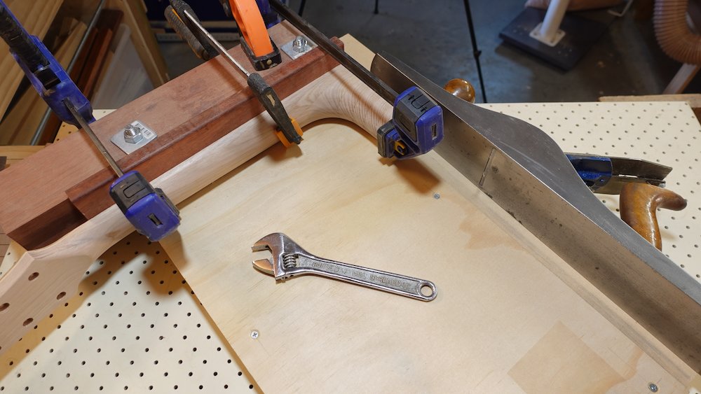
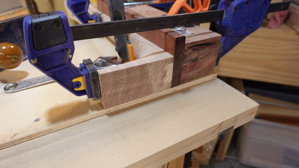
Shooting board run complete |
Minor angle adjustments on sanding board |
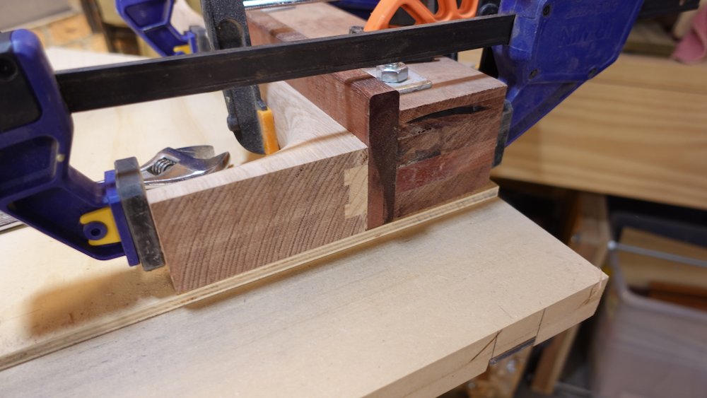
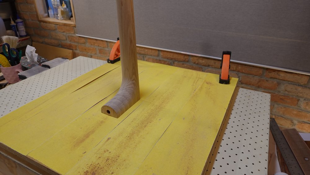
Cut slot in heel for neck-tongue
Use table saw in dado mode, being very careful not to make it too loose
Verticality: if the heel surface is not perpendicular to the body centre line, shim one side with masking tape
Depth: so that there is about 1-2mm of space when tongue is fitted
(Measure tongue extenstion from neck-block assembly in body)
(Be careful not to hit the steel end-nut of the truss rod)
Position (lateral): very careful,
we have already almost finished trimming the top side of neck & fretboard
we will be sanding cutaway portion of neck and body flush
After cutting slot, lower portion of heel will be very fragile
It will be held together by as little as 3mm of edgewise grain
Glue a small block in the bottom portion of the slot, corresponding to the filled-in area at the bottom of the neck-block mortise
Cutting neck tenon slot in heel |
Neck tenon slot cut |
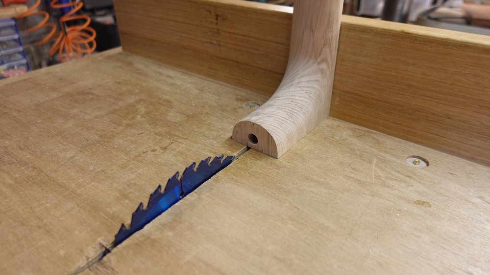
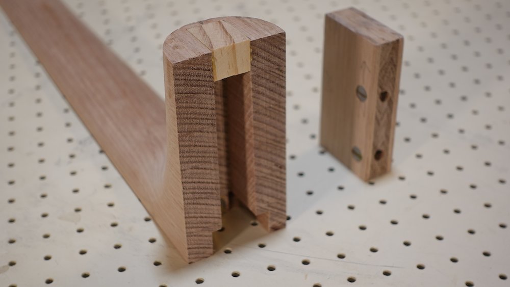
Preparing to fit neck to body
Do as much as possible at this step, as adjusting the heel-face is easier
Neck tongue should now fit into body and neck
Fit to body, use M6 60mm furniture screws, screwed in all the way
Fit neck, check three alignments
Side-to-side (yaw) angle - are the three centres (tail, neck-join, nut) in line?
Up-and-down (pitch) angle - zero in on the neck angle previously estimated, we want a perfectly straight line where the fretboard spans the neck and body
Note that since the soundboard is slightly curved, there will be a small amount of "fall away" at the highest frets.Rotational (roll) angle - does the "roll" axis neck align with the body?
Fix the first two by sanding the butt-end of the neck
Fix the third by shaving and doing shave 'n' shim on the neck tenon (remove from body)
Mark correct height of neck-tongue in neck slot
(there is +/- 2mm of play due to the neck-block slots, so mark the centre position)
Now that we know more about the join, so a little bit more on the bottom side of the neck if required
We want to minimise the amount of neck to remove once fretboard is attached
Especially around the heel
Use neck tongue and do as much as possible on the heel-cutaway join
but leave a tiny bit of the vertical boundary strip proud so that we can sand it smooth after joining
Plan and partially cut heel cap
Option (a) (preferred)
trim heel to an angle matching curved back
heel cap will be even thickness
when gluing on fretboard, temporarily attach a wedge (nails? screws?)
to make a flat surface on the end of the heel to make clamping easier
Option (b)
leave heel straight, heel cap will be a wedge
in this case, clamping is simple when gluing on fretboard
In both cases, plan for it to be flush with back
But leave it proud for now
Don't attach yet
Glue neck-tenon into neck
Use the neck-height mark made two steps up
(doesn't have to be exact, due to the +/- 2mm of play)
Leave two furniture bolts in the tongue, to prevent glue getting into nut threads
Trim the tips off if there is not enough room when fully screwed in
(when doing a dry fit)
Tongue fit should be not too firm, glue will take up space and also swell the wood
Clamping is hard, be careful if you clamp the heel that it stays square in place
Some side clamping is good, but not too tight, don't want to split the grain
Clean off all squeeze out (especially for a glued-in neck)
Take note of the thickness of the thickness of the backing plate
This will needed to trim the clamping bolts to correct length when attaching the neck
Heel cap rough cut, note bevelled edge |
Gluing in neck tenon |
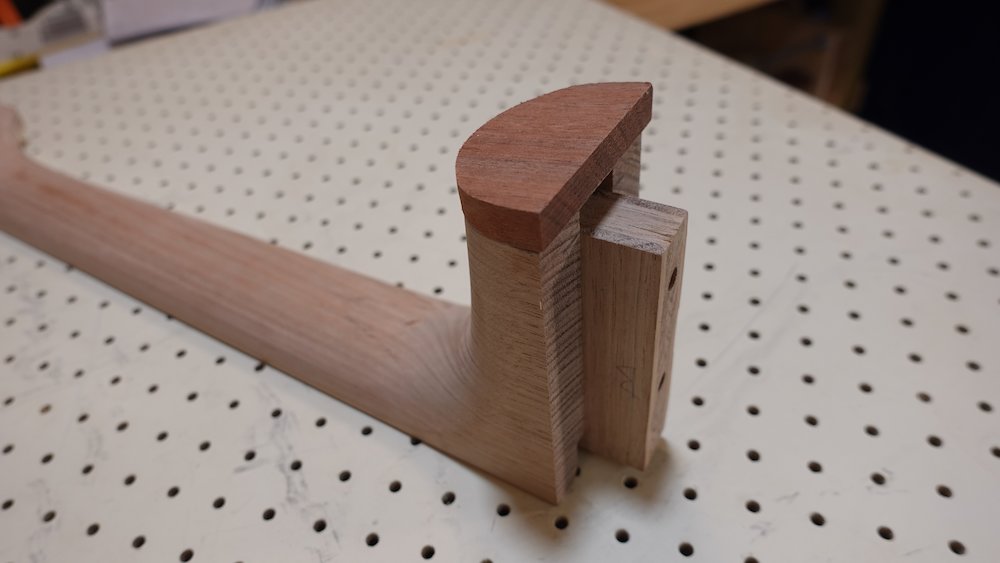
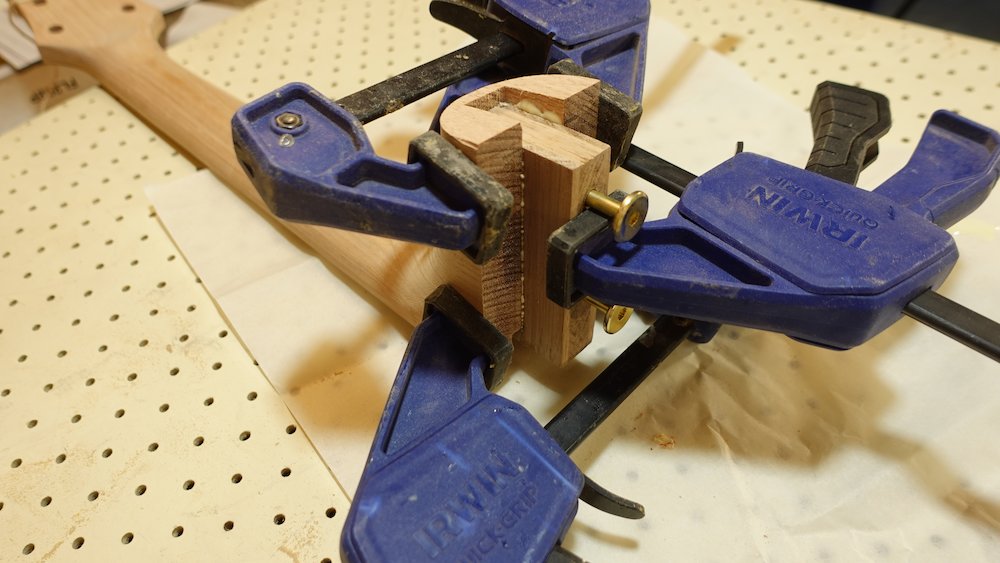
Attach neck to body
This means one of two things
For a glued-in neck, that means gluing in the neck
For the bolt-on neck option, it just means... bolting on the neck
If not done yet, file the notch into the lighter-coloured bindings layer to make everything look concentric/nested (see notes/images in Bindings section)
Determine correct length and trim furniture bolts for clamping
They need to engage with embedded nuts, but not extend further to press against heel
Use furniture bolts to clamp, but make sure neck height is right before tightening
In both cases
Clamp neck to body and check all aligments
Angles can be adjusted by the channeled sanding jig (see image below)
Take care of neck-action (bridge height) angle first,
Then adjust lateral neck angle
In both cases, use oven paper to cover the sandpaper where do not want material removed
Very minor adjustments can also be made by sanding the heel-end of the body
If gluing
Clean of all squeeze out very carefully
Decide whether to remove furniture bolts when dry
the slots are probably better aesthetically
but there's no harm in leaving them in place (though it might give the incorrect impression that the neck is removable)
Adjusing neck angle with channeled sanding jig |
Shave 'n' shim on neck tenon to correct roll |
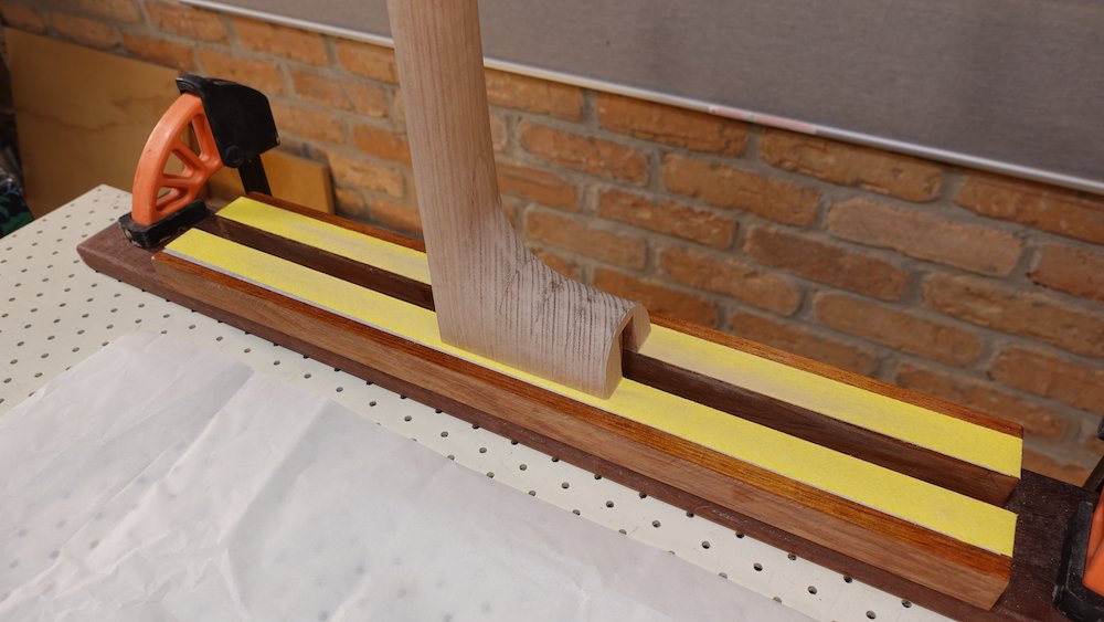
Attend to any coarse levelling required at neck-cutaway join
(will finalise it in the next step)
sand down any remaining proud amount of vertical boundary strip
Temporarily attach fretboard to neck
Since we're following the Finish soundboard first option, just press it down onto the index pins for alignment.
Use clamps if the index pins don't have enough friction to keep it secure
Ensure neck and body under fretboard is ruler-flat
This may require minor sanding, in which case the index pins should be removed (and replaced afterwards)
Heel is either still flat, or has temporary angled block screwed on to make clamping heel area easier
Finalise fretboard, neck and heel fit
Some cleanup will still be required after fretboard is glued on.
Mark the centreline / fullscale line point
Extend that line outwards to string-spacing width at bridge
Use two rulers to extend the fretboard edges, checking that they symmetrically "bracket" this line
Bear in mind that when neck is attached, some re-profiling of neck/fretboard edges might be required
Level heel-cutaway transition
Depending on how perfectly the heel joins the body, levelling might "eat into" the side of the fretboard
If it's less than 0.5mm that's OK, at this stage there is usually about that much "extra"
Remove it and re-flatten that edge against aluminium section sanding bar
re-check symmetry, we don't want the centreline to wander (<1mm is OK)
sand and scrape so fretboard-neck join is near-perfect, which will leave a fragile sharp edge after fingerboard is removed...
Bolt-on neck option: fit fretboard support extension
There may be some lateral wander, existing support piece may require adjustment
Make sure the support extension fits, ready for gluing to the heel and fretboard
Pad out the perimeter so the extension is centred in the pocket
Level the fretboard support extension for a perfectly straight line
NB: sadly, this levelling does not take the thickness of soundboard finish into account
We will have to create some very thin shims to correct for this laterImportant: plan position of support extension bolt and nut: position it forward so that it cannot interfere with the two neck-tenon bolts
Drill 6.5mm hole into fretboard support extension, then into neck block tray
Expand that hole in the fretboard support extension to 9mm, and screw in a threated insert nut
Use a piece of scrap with a 6.5mm hole and an M6 nut to keep the threaded insert square to the fretboard support extension
The butt-end will threaded insert will be slightly proud - either file it down or carefully enlarge the top end of the holeGlue support extension to neck while attached to body:
(Original plan was to glue fretboard, neck and support extension in one step, but that can result in an incorrect angle for the support extension)
Apply masking tape or candle-wax to neck-block surfaces that might be exposed to squeeze-out
Attach neck and tighten tenon-bolts, checking vertical alignment for flush neck-body transition
Glue neck support piece, clamping to required alignment
If desired, fill in any voids on the top side of the heel area
Last chance to do any required shimming and levelling...
Bolt-on neck option: glue on fretboard
Detach neck and glue on fretboard, using the inverse-curve clamping caul to get hairline joins when the neck meets the fingerboard
Cut a piece of M6 bolt, screw it into the fretboard support extension threaded insert bolt so it sticks down.
It will be secured from below with either a wingnut or a fancy knurled nut.
(Later, secure that bolt shaft with Locktite)Attach the neck to the body, testing the two tensioning bolts and the fretboard support extension nut
For glued-in neck: attach a short, bevelled surrogate fretboard to neck to protect the fragile, newly-created sharp edges
(not necessary for bolt-on neck option as we will be gluing fretboard almost immediately)
have it stop just short of the body-fret (so it won't interfere when French polishing soundboard)
also, bevelled down to an edge at that end (same reason)
a little overhang at each side
screwed into the top of the neck
all the handling will round over those sharp edges, resulting in a gap along the fingerboard-neck join line
Levelling neck-soundboard transition |
Levelling neck-cutaway transition |
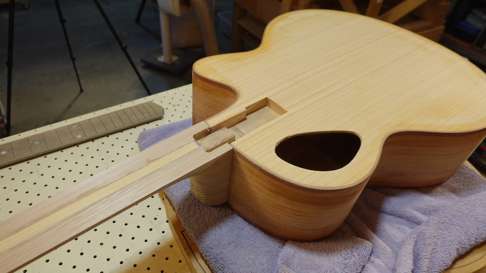
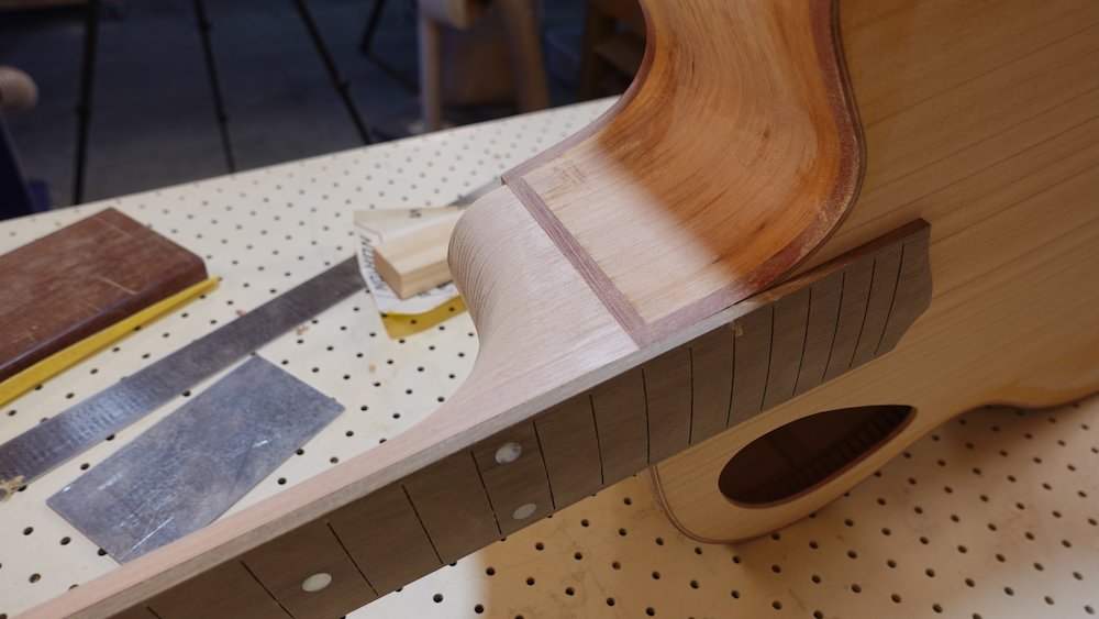
Fretboard support extension pocket |
Adjusting fretboard support extension fit (extreme version) |
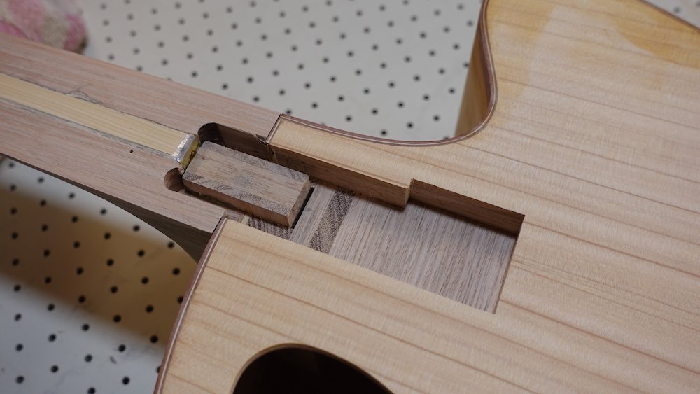
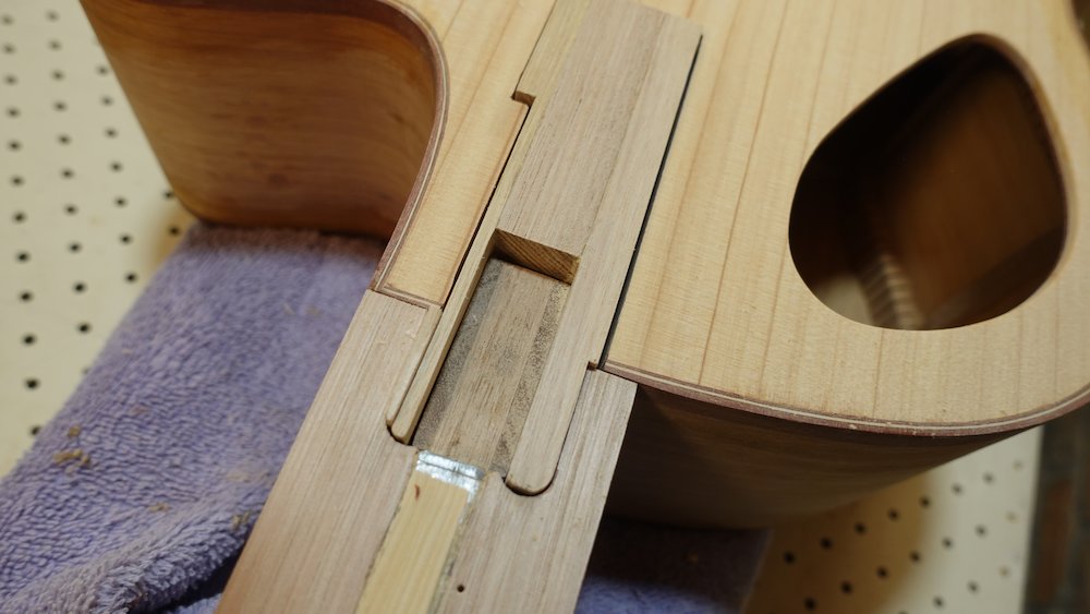
Fretboard support extension attached |
View from underneath |
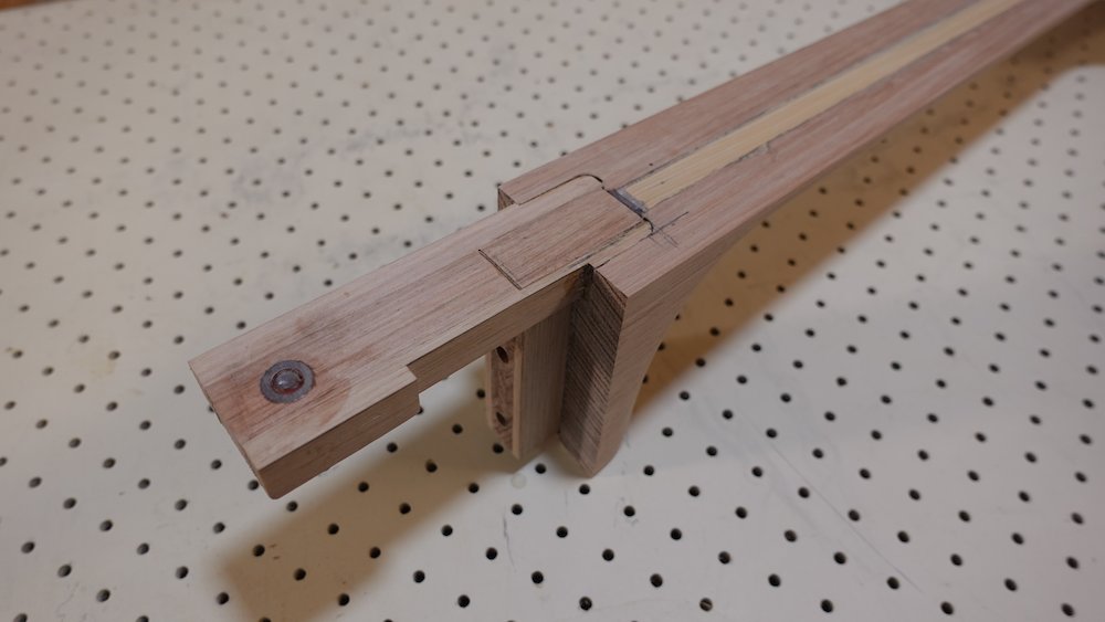
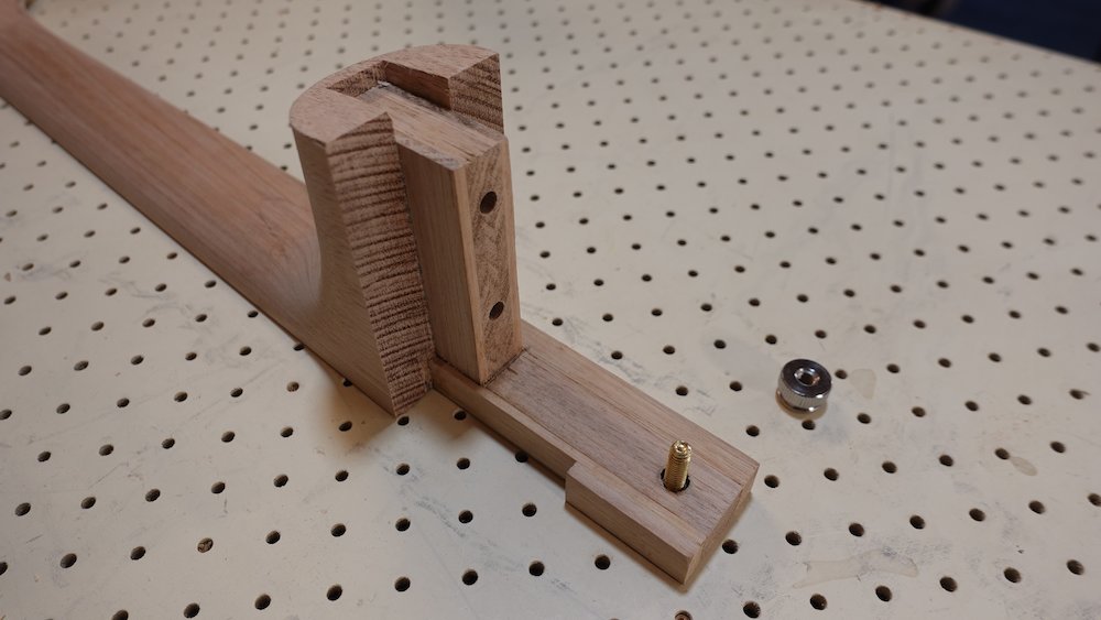
Support extension pocket with hole |
Gluing the fretboard onto the neck (bolt-on option) |
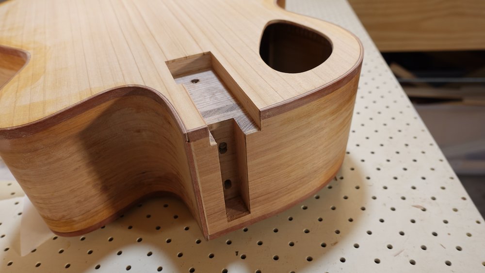
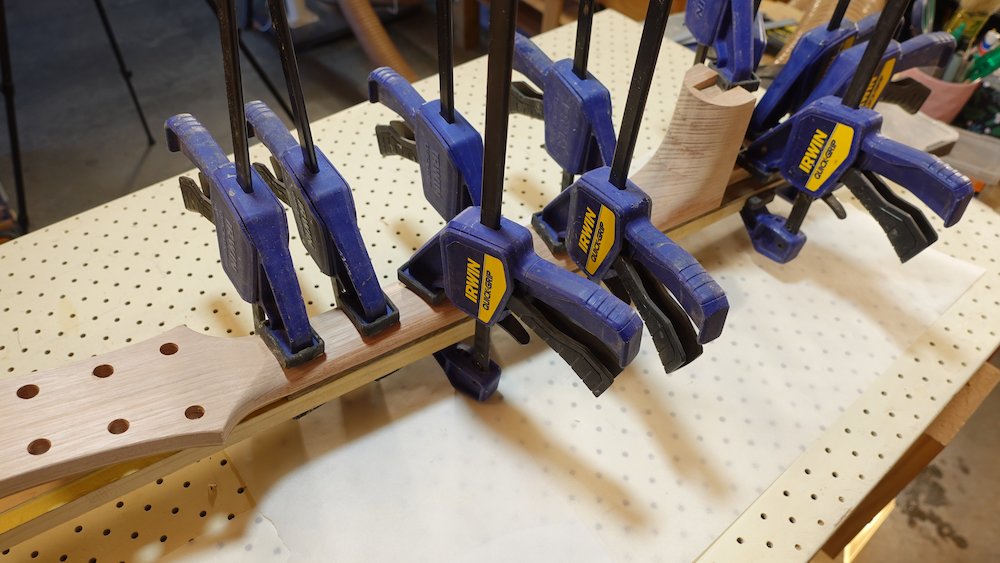
Neck with fretboard attached |
We have a guitar-shaped object |

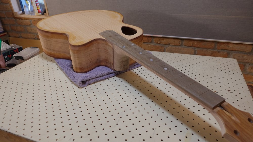
Making bridge
Overview:
Mark full scale line on guitar and finalise required bridge height
Make bridge using either handmade or CNC router method
Drill / enlarge bridge pin holes
Scallop underside of bridge to desired height
Position bridge accurately...
NB: Remember to adjust the Saddlematic to account for the amount we trimmed off the zero fret position
Decide on saddle blank thickness
6-string |
2.5mm or 3.0mm |
12-string |
3.5mm |
Bass |
3.0mm |
Mark full-scale line on soundboard
24" |
609.6mm |
24.5" |
622.3mm |
24.75" |
628.6mm |
25" |
635.0mm |
25.5" |
647.7mm |
34" |
863.6mm |
Both methods
Finalise bridge height as per "Ideal bridge height", above
Ensure fret board is perfectly flat (a tiny amount of upper-fret fall-away is OK)
Cut and mill blank : 152 x 50mm x 1mm more than required depth
(we are going to scallop the underside of the bridge)
Historic method: making bridge by hand
Plan compensation:
Saddle slot is 4.5mm wide
6-string guitars, ~55mm string spacing at saddle
compensation is x..x+3
0 |
11 |
22 |
33 |
44 |
55 |
pins parallel to saddle
12mm back from slot edge
Bass guitars, ~58mm string spacing at saddle
compensation is x..x+4
0 |
19.3 |
38.6 |
58 |
pins parallel to saddle
17mm back from slot edge
12-string guitars, ~60mm string spacing at saddle
compensation is x...x+2 (need to carve individual intonation notches)
String |
Offset |
Delta |
E1 |
0 |
|
E2 |
3.2 |
3.2 |
A1 |
11.4 |
8.2 |
A2 |
14.6 |
3.2 |
D1 |
22.8 |
8.2 |
D2 |
26.0 |
3.2 |
G1 |
34.2 |
8.2 |
G2 |
37.4 |
3.2 |
B1 |
45.6 |
8.2 |
B2 |
48.8 |
3.2 |
E3 |
57.0 |
8.2 |
E4 |
60.2 |
3.2 |
First row 8mm back from low-E bridge slot edge
Second row 20mm back from low-E bridge slot edge
Option #1 - cut saddle slot with table saw, dado-style
Extend compensated saddle line to ends of bridge blank
Current blade cuts 2.6mm slots, so multiple passes to "creep up" on saddle thickness
Use a shim block to offset blank from vertical to get compensation angle
After cutting slot, glue in strips of wood to fill spaces on each side
Option #2 - making the slot on a laminated bridge by using two top-layer pieces
Laminate and mill the bottom layer to required thickness (x-4mm)
Mill the top layer to 4-5mm (corresponding to saddle slot depth)
Mill a strip of timber to the same thickness as saddle to make the two slot-infills at each end
laminate using a candlewax-covered saddle blank and a slotted clamping caul
remove saddle blank after about an hour
carefully clean all squeeze-out from inside of slot
Cutting saddle slot in bridge blank |
Laminated bridge components and clamping caul |
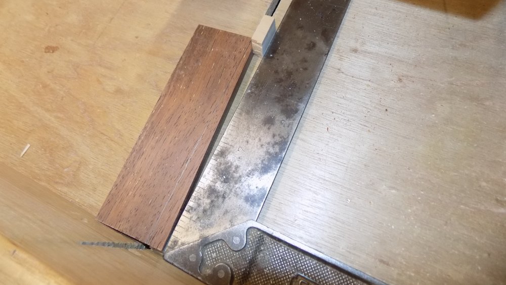
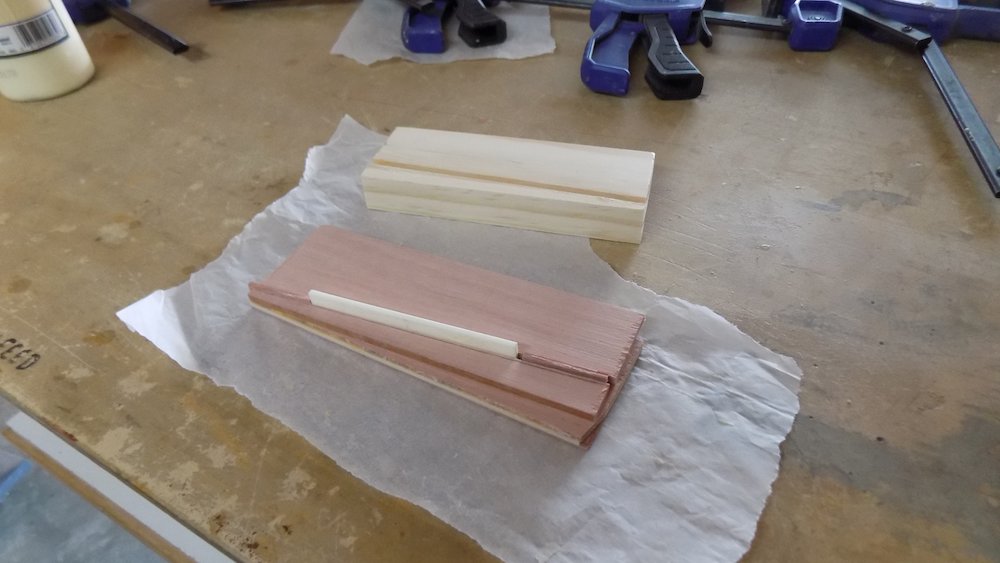
Filling saddle slot ends |
Contouring bridge wings |
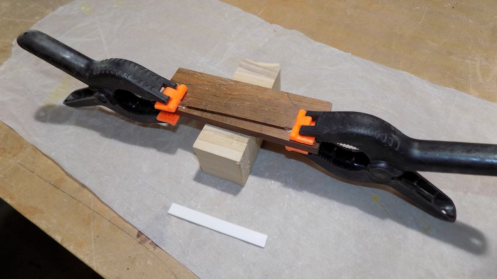
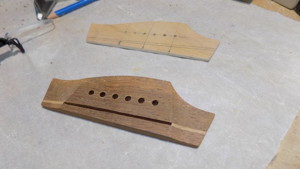
Contouring bridge top |
Finished handmade bridge |
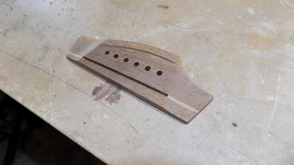
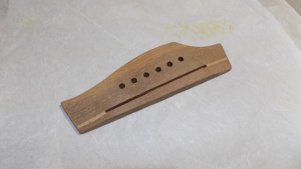
Current method: using CNC rounter to making bridge
CNC carved bridge in 10mm blank
We cut the saddle slot with a separate bit, option or straight or split saddle
Cut well outside outline with bandsaw (to avoid underside tear-out)
Finish perimeter with band sander
Clean up fuzzies and contour lines by hand-sanding
Later, we will scallop it to 9mm in centre, 3mm at wings, giving a weight of ~35g
With correct neck, a ruler, pre-frets, should just touches the edge of the bridge
Later, when frets installed, a ruler should overshoot bridge by about 1mm,
For split saddle option, it is highly recommended to fit saddle blank now,
so that when we get to setup, we only need to deal with a little bit of shellac in the slot
Carving bridge with CNC router |
CNC-routed bridge after cleanup |
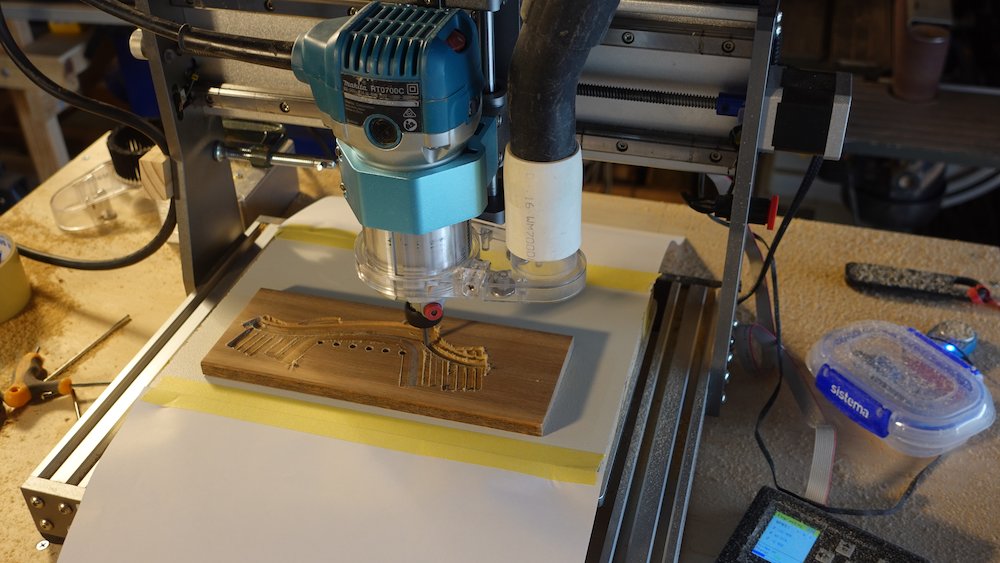
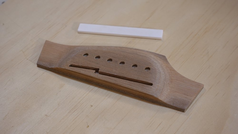
Drill/enlarge bridge pin holes
Hole diameters
Type |
Bridge |
Body |
Regular pins |
5mm |
4.5mm |
Thin-tapered pins |
5mm |
4mm |
Allparts Bass |
8mm or 5/16" |
5/16" |
For handmade bridge with aluminium template
easiest method - clamp template to bridge
drill taking care not to enlarge template holes
very slight counter sink for bridge pin shoulders
Handmade bridge if not using a template
Mark positions using compass point
Then pilot hole punch
Drill in Dremel drill press, 3mm bit, 3mm deep
Position by hand with power off, hold down, drillUse countersink bit to widen shallow holes
so larger drill bit will seat correctlysee diameter table above
very slight counter sink for bridge pin shoulders
CNC bridge
CNC bridge have starter holes, they just need to be drilled all the way through
For basses
NB: Spotted Gum is liable to tear when starting the hole, start with countersunk bit to avoid this
Scallop underside of bridge
Concave transverse bow matching (and slightly exceeding) bow in soundboard: 0.5mm?
Then also a "cavity" scallop (0.2mm?)
Reason: so that we can clamp using bolts through the bridge pin holes
The complex concave curves will serve two purposes
"pull" the soundboard into a slight convex shape
Have "sharper" join-lines around the perimeter
Plan bridge placement
Find and mark lateral placement first
lay a metre rule along each side of the fretboard
should be ~2mm outside of the outer bridge pin holes
equalised = centred laterally
Use StewMac Saddlematic for lengthwise placement
Wait a minute - we have no frets!
take a length of fretwire (doesn't even need to be radiused)
file off the barbs
hammer into the 12th fret slot
remove later
Adjust bridge slot spikes/screws
choose compensation amounts for low and high strings
set pin width to bridge string spacing
subtract half of saddle thickness
NB: VERY important!!!
We have trimmed the fretboard so the zero-first fret interval is shorter!
This means the normal method of using the StewMac Saddlematic will give incorrect results!
Measure the zero-first interval, adjust Saddlematic to add whatever we trimmed off
Alternatively, use a shim at nut-end the same thickness we trimmed off
Bass
String spacing at saddle: 58
Compensation 3.2..7.2
Saddle width 3, so subtract 1.5
Offsets from full scale to inner saddle edge: 1.7, 5.7
Final measurements should be (for 34" scale)
863.6 + 1.7 = 865.3
863.6 + 5.7 = 869.3
(Worrying that this will not be enough if the action is adequately high)
6-string, straight bridge
String spacing at saddle: 55
Compensation 2.3..5.3
Saddle width 2.5: subtract 1.25
Offsets from full scale to inner saddle edge: 1.1, 4.1Saddle width 3.0: so subtract 1.5
Offsets from full scale to inner saddle edge: 0.8, 3.8Final measurements should be (for 25.5" scale, 2.5mm brige)
647.7 + 1.1 = 648.75 (648.5 for 3mm bridge)
647.7 + 4.1 = 651.75 (651.5 for 3mm bridge)for 24.75" scale
628.7 + 1.1 = 629.8 (629.55 for 3mm bridge)
628.7 + 4.1 = 632.8 (632.55 for 3mm bridge)
6-string, split bridge
String spacing at saddle: 55
Compensation 2.1..5.4
Saddle width 3.0: so subtract 1.5
Offsets from full scale to inner saddle edge: 0.6, 3.9Final measurements should be (for 25.5" scale, 3mm bridge)
647.7 + 0.6 = 648.3
647.7 + 3.9 = 651.6for 24.75" scale
628.7 + 0.6 = 629.3
628.7 + 3.9 = 632.6(Bridge edge should be perpendicular to centre line)
12-string
String spacing at saddle: 60
Compensation 2.25..4.25
Saddle width 3.5, so subtract 1.75
Offsets from full scale to inner saddle edge: 0.5, 2.5
(Cannot get StewMac pins that close, consider using outer edge)
Final measurements should be (for 25.5" scale)
647.7 + 0.5 = 648.2
647.7 + 2.5 = 650.2for 24.75" scale
628.7 + 0.5 = 629.2
628.7 + 2.5 = 631.2
Positioning bridge laterally |
Positioning bridge lengthwise |
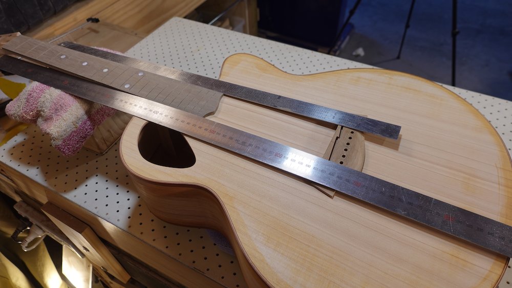
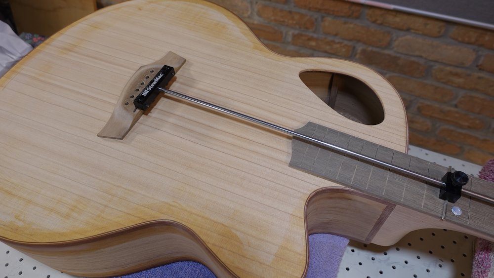
Drill bridge pin holes in body
Put a layer of masking tape down so we can trace bridge position with pencil
Position bridge and trace around perimeter with a sharp pencil
Overlay a modest amount of double-sided tape
Note: the aim of the tape is to keep the bridge steady while we attach the C-clamps.
The aim of the C-clamps is to keep the bridge steady while disturbing it with the drill.
Then we need to remove the bridge without damaging the soundboard.
This has proved tricky in the past, which is why we now do this step earlier.Place some upside-down fibreglass-reinforced tape near ends, to assist when removing the bridge.
Position bridge in the exact position of the traced outline and press down.
Use the peeled off wax paper to fine tune position before sliding it away and pressing downAttach and tighten the C-clamps
Using an imperial drill bit just smaller than the bridge holes as a punch,
make starter indentations by tapping gently while rotating the bit between hits.
For guitar (5mm bridge holes), use a 3/16" bit
For bass (8mm bridge holes), use a 5/16" bitUsing that same bit, drill starter indentations only in the two innermost holes
For guitars, it might be possible to drill the four innermost holes.
The C-clamps mean we cannot drill the outermost holes
The slightly smaller drill bit minimises the risk of the bridge moving.Important: change drill bit to smaller (body) diameter!
Remove the C-clamps, finish drilling the innermost holes, holding some scrap underneath for a clean exit-wound.
If really confident in the steadiness of the tape, drill all holes...
Otherwise, bolt down the bridge with 3/16" countersunk bolts (top) and wingnuts (underneath)
NB: don't over-tighten, or there'll be mismatched counter-sinking to fix!Finally drill the outermost holes
Optional: check using actual bridge pins, which of the holes are accurate enough to repeat exact positioning of bridge later
Alternative approach
Use the two C-clamps to make sure double-sided sticky tape is secure
Move the clamps back and forth to make room to drill each hole, making sure one is tight before moving the other
Setting up to drill bridge pin holes |
Four inner holes drilled and secured |
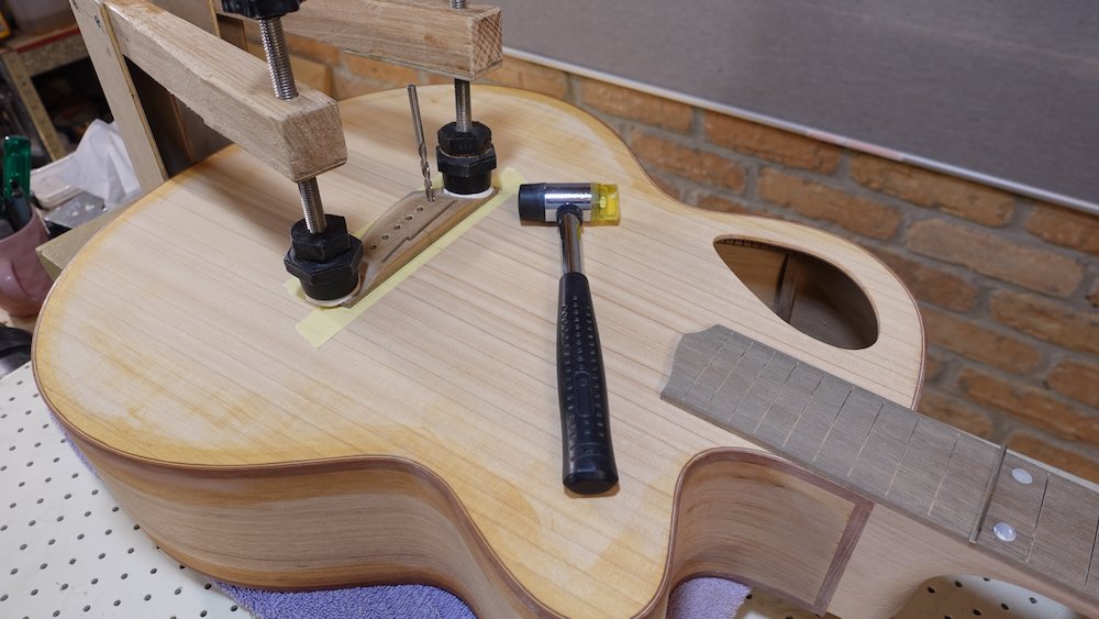
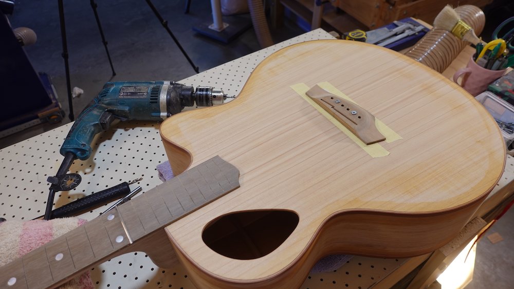
French polishing soundboard
Overview:
Only do this now for glued-in neck option
Sand, round-over, grain-fill soundboard if required
Mask bridge and fretboard areas
French polish to spriting-off stage
Decide whether to French polish soundboard first
Yes for glue-in neck
No for bolt-on neck option
Sand soundboard to final finish-ready smoothness
Round-over bindings (soundboard side)
Decide whether grain filling is to be done
NB: The answer is yes it must be done, at the very least to the sides
If using grain-filling
Position bridge, mask bridge and fretboard with magic tape (as per details in following sections)
Apply grain filler
Remove mask, sand filler down to wood
If feeling on a roll, do back and sides as well, though stay away from heel cap area
Mask bridge position & fretboard for French polishing
Reposition bridge
if all is going well, bridge pins will suffice
double-check with position with rulers
Put strips of Scotch/magic/invisible stickytape where bridge will be
But first, put a piece of paper down in the middle - to make removal easier when French polishing is complete
fold over ends of tape- starting a peel is difficult
since Scotch tape lifts fibres when peeled off, don't rub it down hard
Position bridge
if bridge pins are not 100% accurate and stable, use the bridge clamping jig (see notes on attaching bridge, below)
trace around bridge perimeter with a sharp pencil (can draw on Scotch tape)
NB: on softer soundboards like Huon pine, the pencil will score the timber through the tape.
try an additional layer of paper attached with double-sided tape.
attach inner bridge mask (aluminium template 1.0mm inside the bridge perimeter)
use bolts and wingnuts
position so that it is perfectly centred 1.0mm inside the traced outline
if it isn't perfect (bridge has been sanded to a slightly different shape), reposition the template for each line segment
use this template to cut the outline - inside the bridge position
shellac remains rough in sticky tape edge's lee
peel away excess tape, leaving bridge area masked
make sure tape is firmly attached (ok to rub down now, this area will be covered by bridge)
put an extra piece to cover the holes used to bolt down the inner mask template
Glued-in neck option: repeat steps for area of fretboard that is over body
Historical note:
Before the Finish soundboard first option, at this stage we would:
simply mask entire fretboard
French polish soundboard
NB: make sure rubber surface is clean - fresh cloth recommended
French polish the soundboard only - long uninterrupted strokes for the win
After the sealing / flood-fill stage, some timbers may exhibit raised grain
- do an additional levelling step at this stage to address this if neededNB: sticky tape in the two masks may become lose and shed flakes of shellac, which then adhere to the guitar and need to be sanded down (1200 sandpaper & oil)
See French polishing notes below
Stop before "spiriting off" stage, wait until finishing rest of guitar
When complete, leave on all tape masking for now
Bridge position traced onto magic tape |
Bridge mask inner template attached |
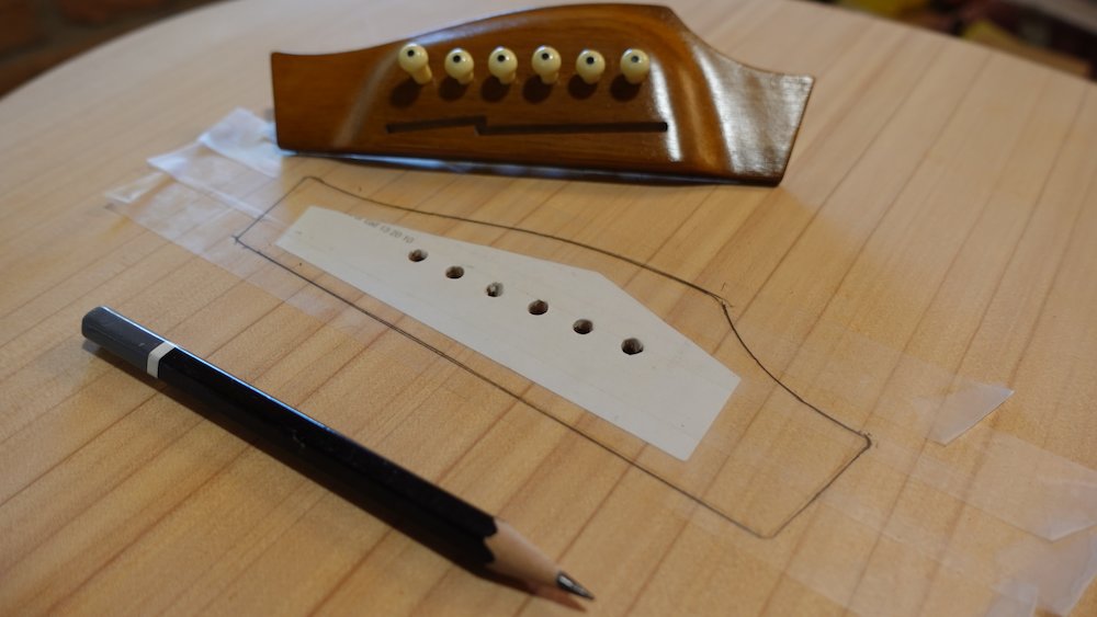
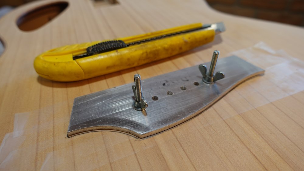
Bridge mask cutting complete |
Starting to French polish soundboard |
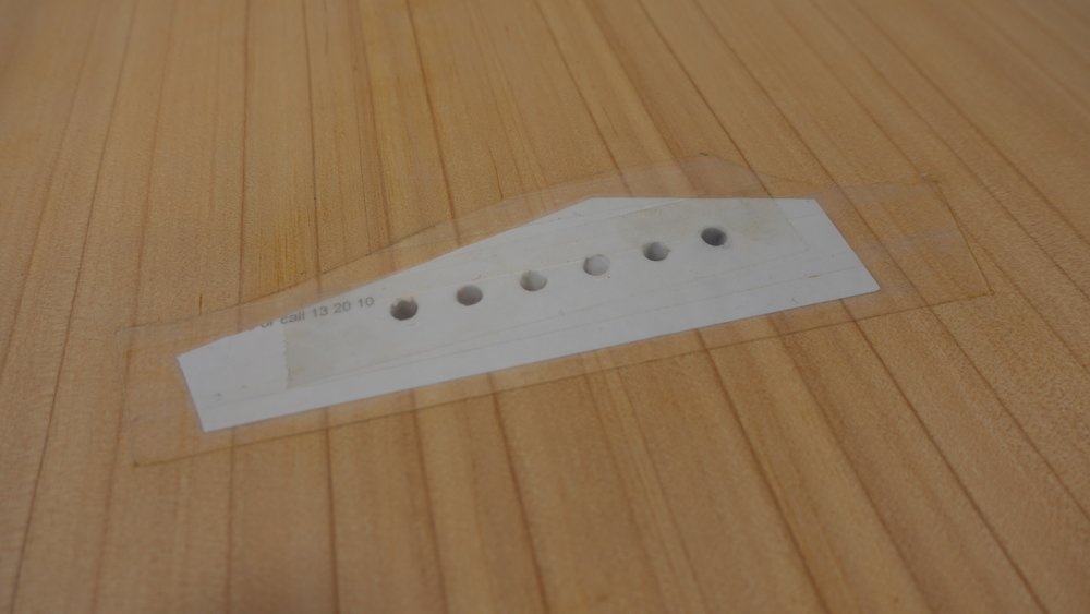
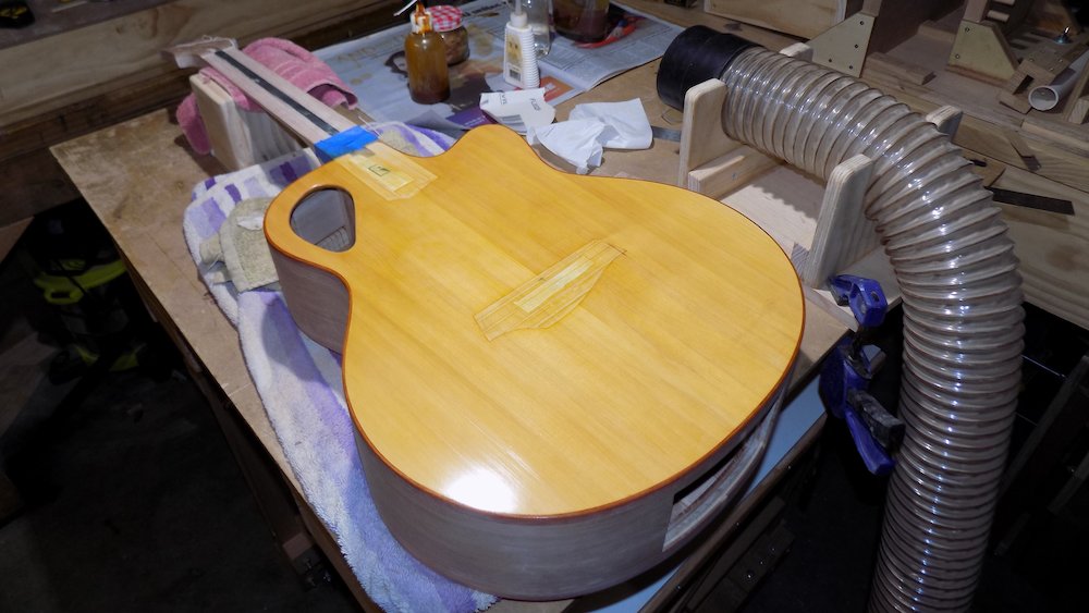
Complete all construction steps deferred due to the Finish soundboard first option
Overview:
Make truss rod cover and pickguard (if required)
Glued-in neck option: glue fretboard to neck
Attach heel-cap and finish still-proud transition to back and heel
If bolt-on neck option, sand heirloom fit round-over along heel-body edges
Final sanding, round-overs, gap- and grain-filling
Make truss rod cover and pickguard (if required)
Truss rod cover may need to have an indentation in the bottom singe truss rod nut pokes up a bit
Initial design was a simple ogival arch
I now have a more complex narrower design that can be removed while the strings are tensioned up
Mill some fingerboard/bridge wood
Truss rod cover
Truss rod nut almost certainly protrudes above headstock
Cross-ply lamination is a good idea, though it can make the stock curve
Mill (and optionally laminate) to required width
(3mm seems to be pretty common, allowing 2mm truss rod nut protrusion)
We used to do this by hand, we now use the CNC router
Drill / excavate a furrow in the underside, for truss rod nut to fit into.
If not using CNC rounter, a Dremel spindle sander is good for this.
Cut a 14-degree under-bevel so it butts up nicely with the back of the nut
Pickguard
Rip to 70mm (GP), 65mm (parlour), (generally don't do bass)
Mill to 2.5mm
Shape, sand, fill grain with Timbermate or Feast Watson sanding sealer, sand
Cutting truss rod cover cavity with ball-nose bit |
Pickguard and truss rod cover before grain-filling |
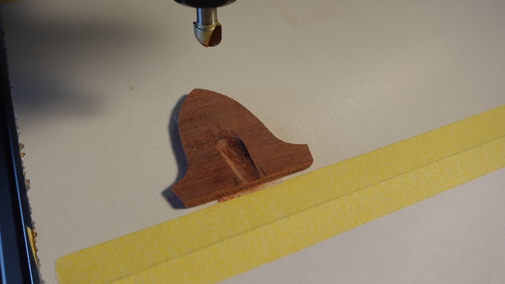
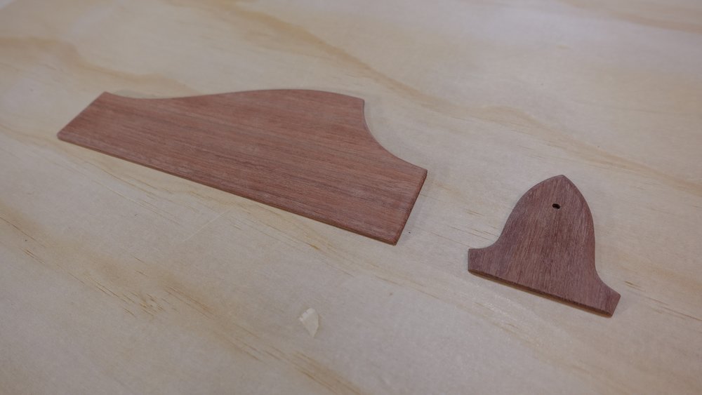
Glued-in neck option: glue fretboard to neck
(Already done for bolt-on neck option)
NB: do a dry run clamping first, for the following reason:
check for any gaps
final check fingerboard width is correct
Remove fretboard tape masking from soundboard
Everybody on the internet keeps glue off the truss rod,
This makes sense for exposed-rod designs
It makes no sense at all for the Martin enclosed channel model
A small piece over the truss rod nut might be a good idea though
Use inverse radius dual-curved clamping caul, it makes it a breeze
Clean off all squeeze-out carefully with moist cloth or kitchen wipe
NB: use more clamps than in image below
The temporary heel clamping wedge |
Gluing on the fretboard (glued-in neck option) |
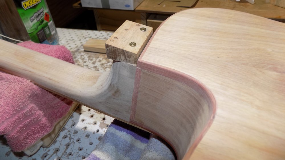
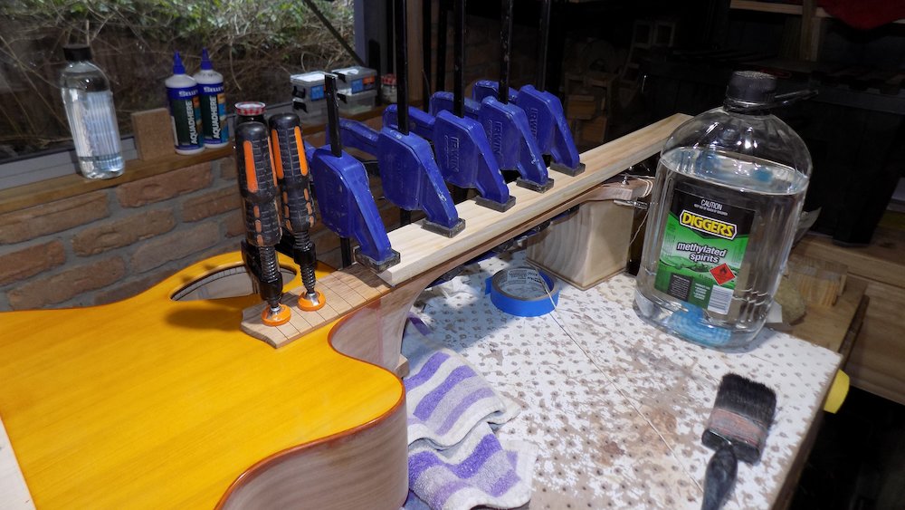
Attend to any minor sanding of the fretboard-neck join
Most of the fitting was done earlier, we're really just finessing the glue joins
Finalise smoothing the heel-cutaway transition
Attach heel cap
Clamp with a regular clamp and index pins
(If neck is glued in, can also use semicircle-cutout clamping caul with bungy cord)
Finish carving still-proud transition to back and heel
Bolt-on neck option
Sand a tiny heirloom fit round-over along all heel-body join edges
This will legitemise any miniscule unevenness due to the neck not being glued in
Attaching the heelcap (glued-in neck option) |
Heelcap carving finished |
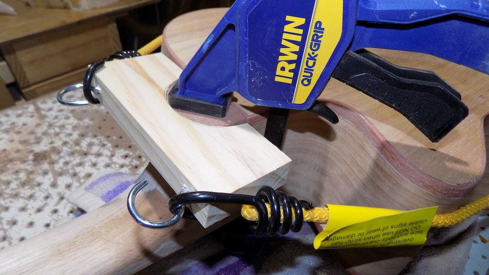
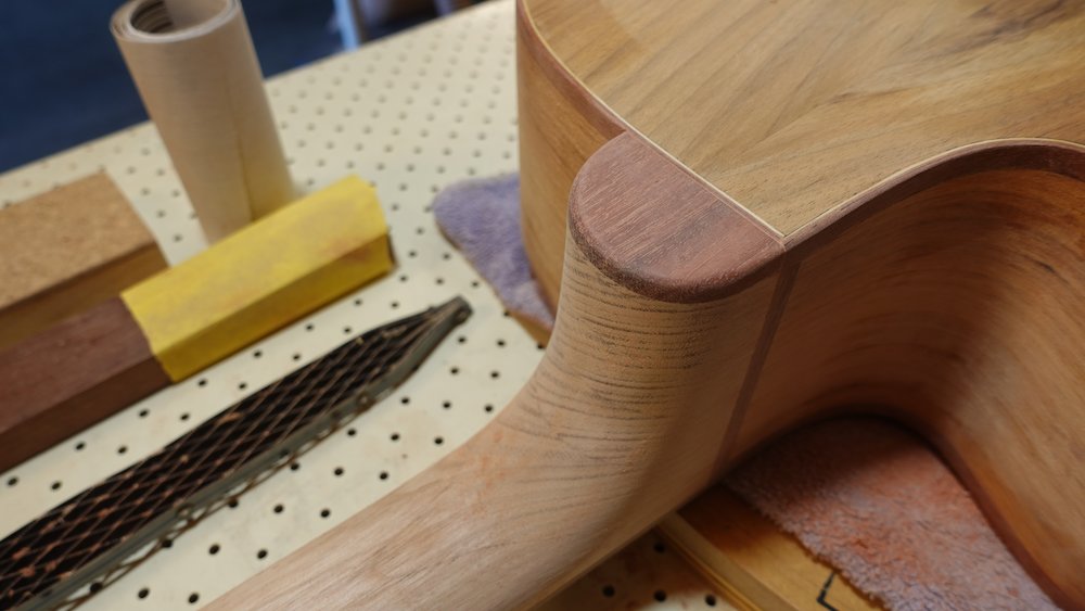
Final sanding, rounding over bindings edges, void-and-grain-fillings
Final check for gaps - fill with glue and appropriate sawdust (or other product)
Grain-filling
Timbermate water-based filler - various colours - diluted with water
- works-ish, but balance between under- and over-sanding is very fineFeast Watson sanding sealer?
- works-ish, but leaves some unfilled micro-voids. Over-sanded?At a bare minimum, grain-fill the sides. The back can usually be managed with shellac,
and the soundboard (on which we like thinner finish) may have its own "levelling raised grain" measures later.
If using commercial sanding sealer, don't sand immediately - it likes a longer cure time.The sides may still be marked with shellac, don't fret too much.
(Very dark areas probably indicate inadequate sanding.)
Putting sanding sealer over modest shellac marks is quite OK.
Installing frets
Overview:
Make truss rod cover and pickguard (if required)
Glued-in neck option: glue fretboard to neck
Attach heel-cap and finish still-proud transition to back and heel
If bolt-on neck option, sand heirloom fit round-over along heel-body edges
Final sanding, round-overs, gap- and grain-filling
Bend fretwire, cut to length
Bound fretboard option: snip off tang at each end
Install frets
Snip off ends
File flush vertically, then 35-degree angle
Dress fret ends
My fretwire choices
Instrument |
Part # |
Name |
Inches |
mm |
Guitar |
152 |
Oversize Medium |
.092 x .048 |
2.34 x 1.22 |
Bass |
149 |
Jumbo |
.103 x .046 |
2.63 x 1.16 |
Glued-in neck option
we have to install and dress the frets without damaging the soundboard!
Bolt-on neck option
we can install and dress the frets on the detached neck! (w00t!)
Important (if glued-in neck option)
Before installing frets, tape two pieces of cardboard
to the body where the fretboard is glued to it.Do not rely on masking tape, even multiple layers.
When snipping fret ends, the pieces will fly off with great force,
chipping the soundboard wood (or the finished surface).Make sure the cardboard is sealed around all edges,
to prevent metal filings from finding their way underneath.
Radius sanding block says 11" (from 22" cymbal),
better to bend frets to a tighter radius(ie, 16" cymbal or 14" snare)
I hgave also tried a 10" radius, but hammering approach must be different (see below)
My bending wheel is not perfectly even, the remedy is to keep removing fretwire
and reinserting with crank at different clock positions
Multiple passes at different clock positions
Turning fretwire end-on-end each pass
Each pass goes all the way (piece comes out of machine each time)
After cutting fretwire into lengths
dull any sharp edges, so as not to cut fingers while hammering
Fret slots are too tight
StuMac recommends against widening them,
promoting a barb-shaving device
I got good results by dragging a compass spike along them
it doesn't remove wood, just stretches the slot
BUT... be very careful it doesn't jump out of the slot and scratch the fretboard!
Ben from Crimson Custom Guitars uses a triangular file
Fret slots are too tight (level boss version)
For bound-neck option, I have found that installing frets requires a lot more force
This may be caused by the fact that the slots are "fully enclosed"
Solution to this is a work in progress
Bound fretboard:
slots need to be cleaned
a box-cutter knife blade with the sharp section ground off, can be useful (see image)
Hammering works best with a radiused, hardwood, end-grain caul
Tap one end in, not fully
Work towards middle,
Then other end
Then use hammering caul to get it fully seated
NB: if bending frets to a 10" radius, start at one end, then middle, then other end
Be very gentle when hammering over body (glued-in neck option)
Considing using an adjustable support strut underneath soundboard
Use rockers to make sure each fret is perfectly seated along its length
The use of glue on virgin slots (widened or otherwise) is debated
I have tried several ways of using CA, without satisfaction
My preferred method is to spread a small amount of some Titebond over the open slot before hammering
Slot cleaner for bound freboard option |
Bending the fretwire |
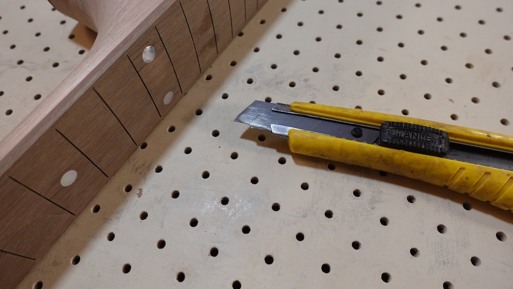
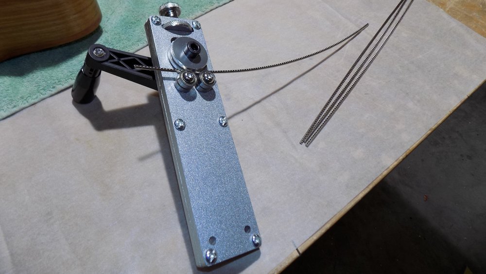
Tools using for installing frets |
Cardboard protection for the soundboard |
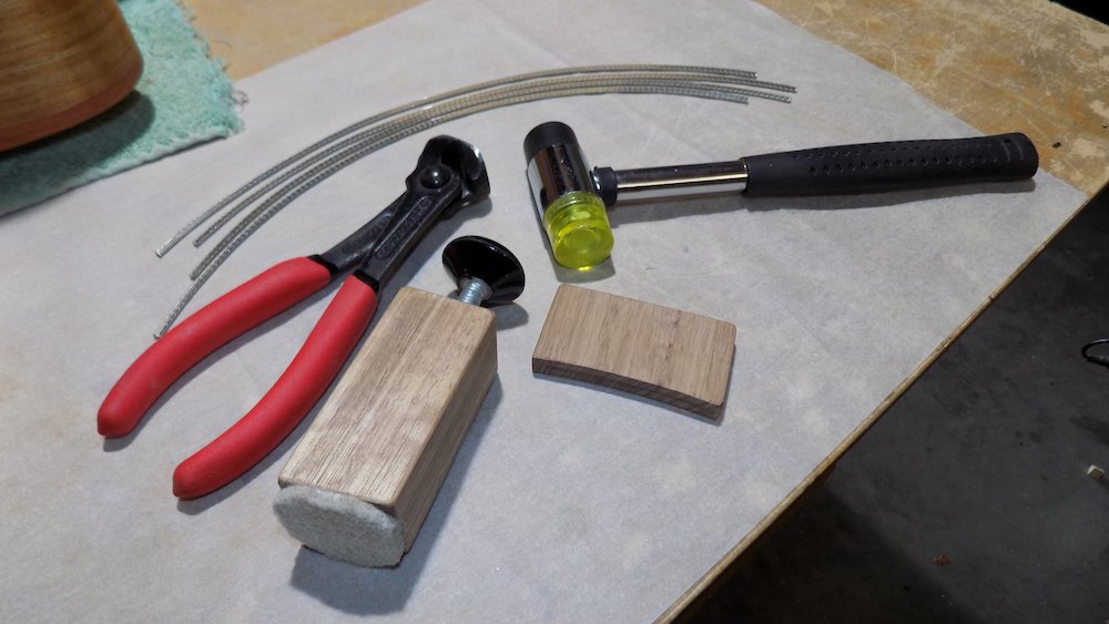
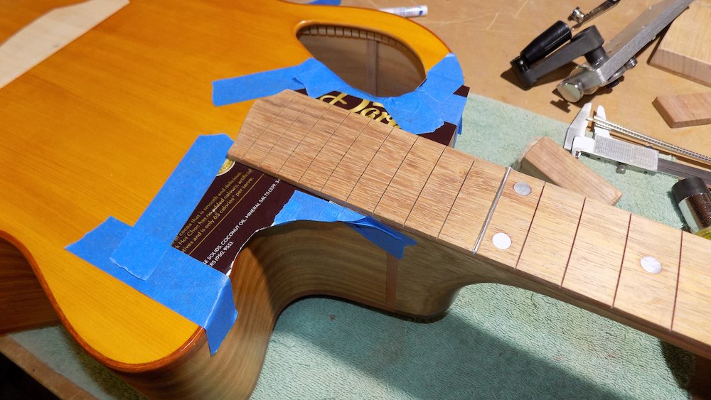
Adjustable support strut for upper frets |
First few frets tapped in |
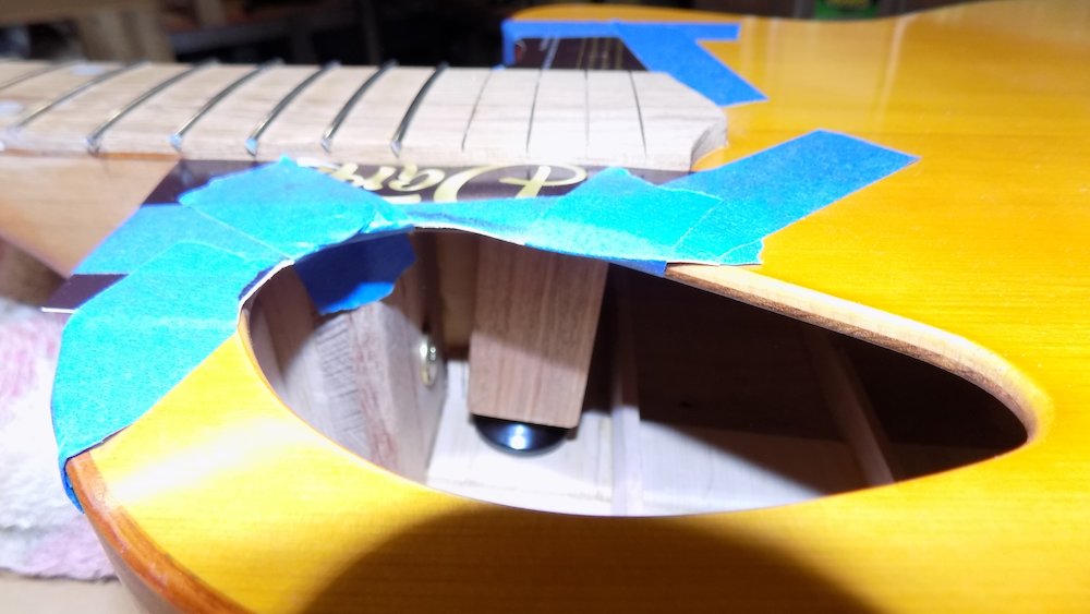
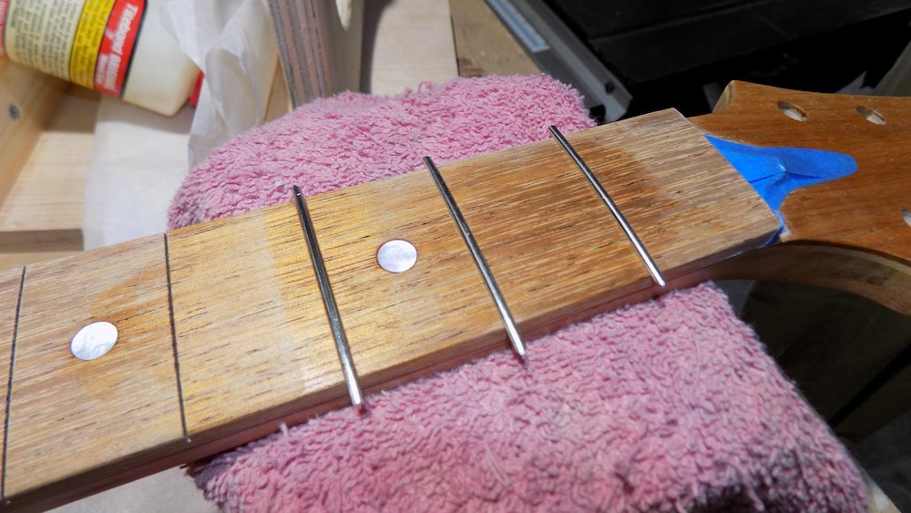
Snip off fret ends
Just in case the cardboard is not adequate, rest scraper against edge of fretboard for extra protection.
File fret ends vertically level using vertical file-holder jig with bevel
NB: ensure bevel sits on frets, so that file stays perfectly vertical
and doesn't cut into side of fretboardbe very careful not to slip and mark frets or sides of fretboard
File 35 degree bevel using 35 degree jig
be very careful not to slip and mark frets
Check that the fret tops are perfectly level
While filing the ends, any vertical bumps indicate high frets
In some cases, imperfectly seated frets can be fixed with the fretting hammer
In others, the aluminium sanding bar, with very fine grit sandpaper, will be needed
If sanding has been done, re-crown the affected frets with crowning file
Fret-end dressing
This for semi-hemispherical fret ends that look (and feel) so nice...
Using flat-bottomed file, grind in circular end-profile from above
This may leave "razor-blade points" at each corner, as we were filing in from the side
Remove (or almost remove) those points by filing from above very gently to avoid filing down the fretboard
With fret-crowning file, round over the fret ends from above, also putting in some side-to-side and rocking motion
Coarse steel wool, first across the fret ends, then along the edges of the neck
Frantically try to improve things with 1200 sandpaper, more steel wool, Fret Erasers etc
All frets tapped in (bound fretboard) |
Fret end file guides |
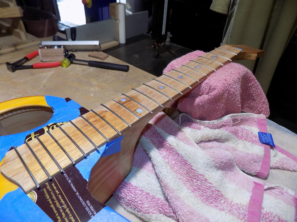
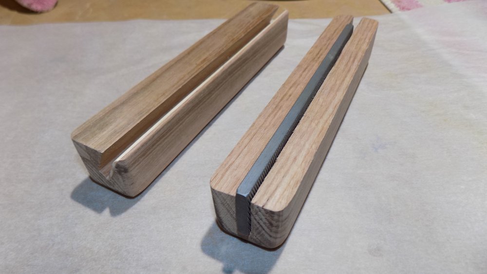
Fret end dressing file |
Fret ends dressed |
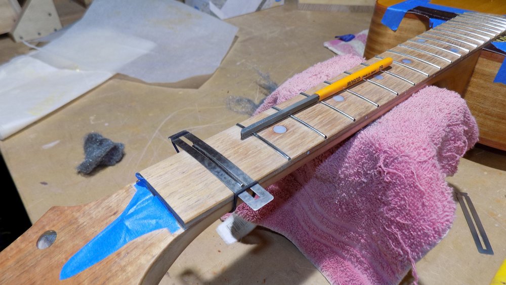
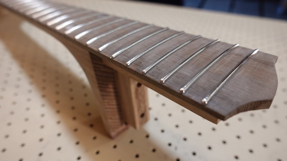
French polish rest of guitar
Overview:
Double-check all prep steps: access port cover, bindings round-overs, void- and grain-filling, final sanding
Bolt-on neck option: consul "French polish soundboard" section for masking bridge position
Tape off fretboard
Prepare access port cover, bridge, truss rod cover and pickguard with bolts/blocks for holding
Seal/flood-fill with waxed shellac
Check for raised grain, inadequate sanding
Build until colour is right
Switch to clear shellac
Build until gloss is right, levelling if required
(Postpone spiriting off until bridge is attached)
Before beginning
Double-check access port cover is level
Remove access port cover, deepen countersink holes for screws if sanding has left them too shallow (annoying to do this after French polishing it)
Bolt-on neck option
Follow "French polish soundboard" section above, especially the bits about masking the bridge position
Tape off fretboard with masking tape
leave most of the sides exposed
this will allow the shellac-lemon-oil transition to be more easily sanded down
Finalise filling grain, sanding etc.
Prepeare shellac
* Three-pound cut
50g flakes, 140ml methylated spirits
Industrial methylated spirits, or dry normal methds with oven-dried tapioca
Mix fresh, some days to dissolve completely, filter if any sediment
Current French polishing strategy
seal / flood full / initial build with waxed shellac for best colour
when colour is good, switch to unwaxed shellac for better gloss and sandability
use a transitional rubber first, so the unwaxed rubber can stay clean
when levelling unwaxed shellac (or repairs down the track), less risk of ending up with uneven colouring
Apply finish to guitar, bridge, truss rod cover and pickguard (if there is one)
Seal first - use thinner cut, cloth or brush,
don't use a rubber that has seen oil when sealing
NB: immediately after sealing, check for inadequately sanded scratches, and fix them!
Build up sessions
Level micro bumps with 1200 sandpaper + oil
be very careful not do break through finish layer - it is very soft when being worked
declog sandpaper with clean cloth
Optional: cut to matt with 1500, avoiding edges
For a deep, gloss finish, this can be done twice
Pay attention to edges around soundboard:
since that was done in an earlier session, there might be some unevenness
can be sanded down with 1200 + oil
Difficult area (glued-in neck option): neck to upper-side join
use pointed pad to get into corner
Spiriting off
consider postponing soundboard until bridge is attached
separate rubber
alcohol only, very lightly charged
no oil - the point is to remove the oil
also remove swirl lines (and put in much, much finer ones)
should bring up gloss
need to apply some pressure
multiple sessions to avoid it starting to grab
Final steps?
As with spiriting off, consider postponing soundboard until bridge is attached
Finest car polish??? With ultra-fine cutting compound.
Must wait a week, so that polish is completely dry & hard
Wax / liquid furniture polish???
make sure it is dry so it doesn't pick up fibres
Be very careful of the face that rests on the towel
Blocks to hold small pieces while French polishing |
French polishing progress |
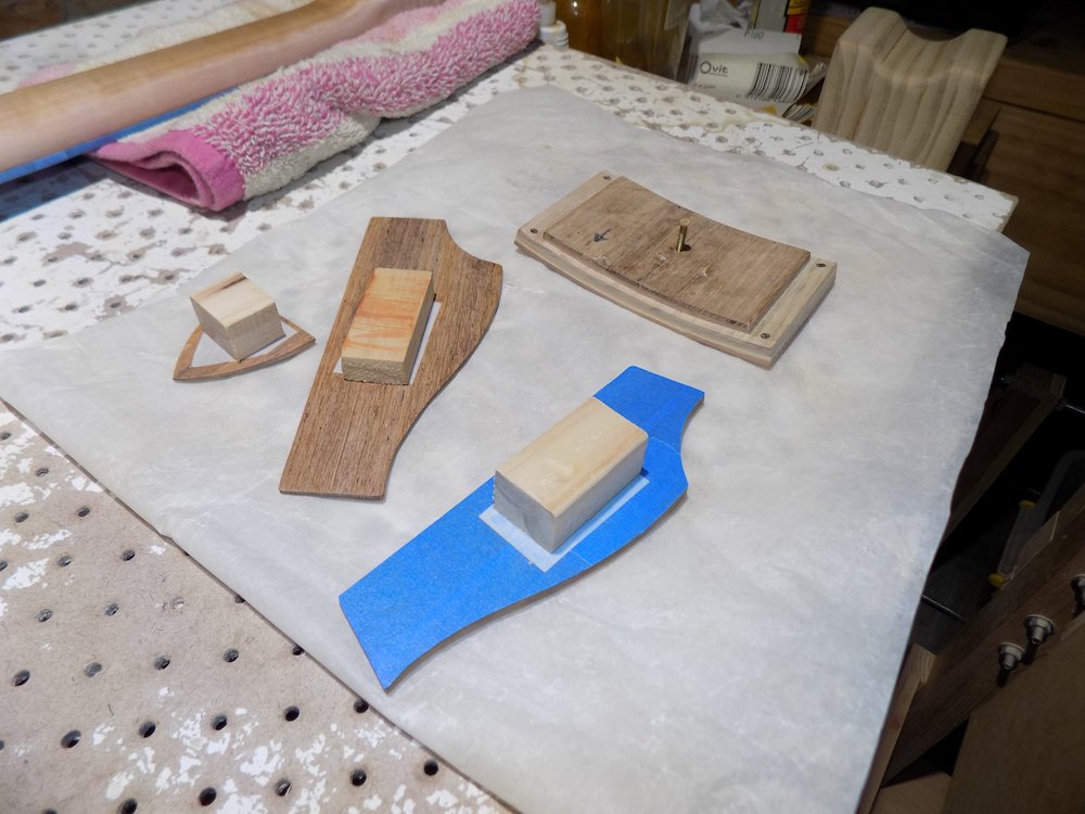
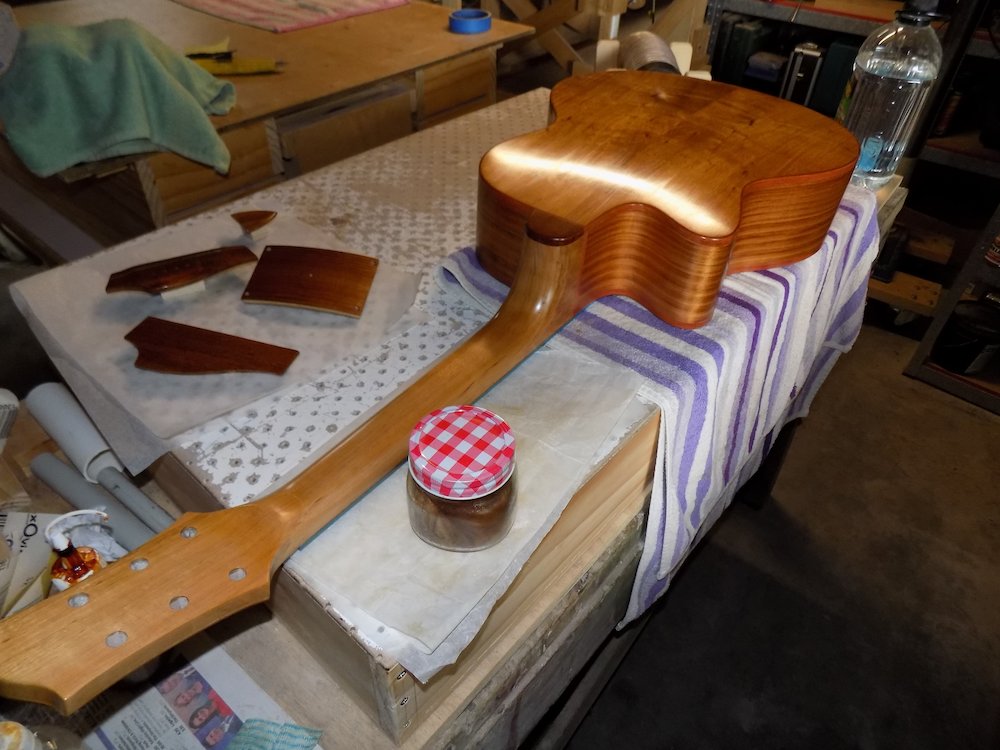
Remove masking from fretboard and finesse fretboard-shallac transition
use 350 grit sandpaper to "bevel" the portion of shellac that is on the fretboard
be careful not to touch the actual neck
apply lemon oil to the fretboard when done
if the shallac and/or neck join transition is still troublesome to feel...
... try 1200 sandpaper + oil, minimising the amount of neck touched,
... a little bit of auto polish afterwards if required
Attach bridge
Overview:
Make sure bridge blank fits into slot
Remove bridge mask, trim the shellac "ridge" that builds up around perimeter
Glue in bridge using clamping jig
Ream bridge pin holes to final diameter
Finalise finish - spriting off, car & furniture polish
Attach tuners and strap buttons
But first, sand shellac from inside edges of saddle slot, so that saddle blank fits in firmly but not too tightly
Don't do this until shellac finish on bridge is hard.
Masking tape will lift incompletely-cured shellac, and the clamping bolts/caul will deform/mark it.Use appropriate drill bit to clean up bridge pin holes after finishing
Remove masking tape from bridge position on soundboard
attach the outer bridge mask (aluminium template 0.5mm inside the bridge perimeter)
position some pieces of masking tape at an even distance (1.0mm?) from the shellac edge
bolt in place and position it so that it is evenly balanced - use masking tape markers, as it will obscure the border
use it as a template to trim away the uneven "ridge" shellac around the perimeter
Glue in bridge using bridge clamping jig
make sure aluminium under-bracket matches scalloped curve of the underside of bridge
resulting compression should apply enough pressure to the bridge "wings"
However, small pieces of 6mm MDF can be inserted between jig and wings for additional pressure
After glue is dry, remaining hole(s) can be drilled if not done so already
Need to wait until clamping bolts are removed so a piece of scrap can be held underneath
Ream bridge pin holes to size
shoulder rings underneath heads should nestle into the countersunk rim
After getting one right, use masking tape around reamer
The shellac ridge around the tape mask |
Masking tape to mark bridge position |
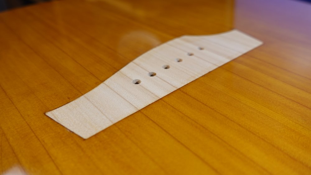
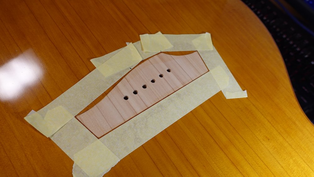
Bridge trimming guide attached |
Shellac ridge around edges trimmed |
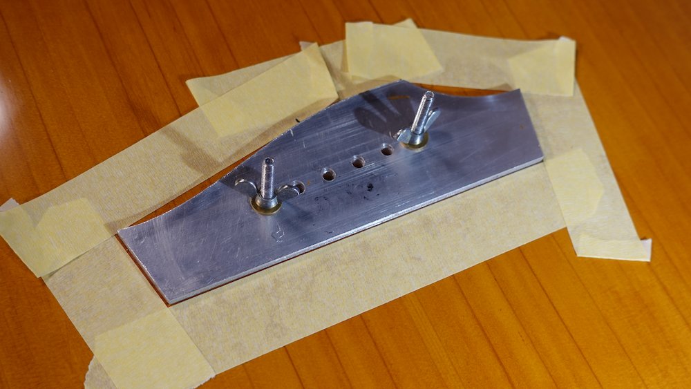
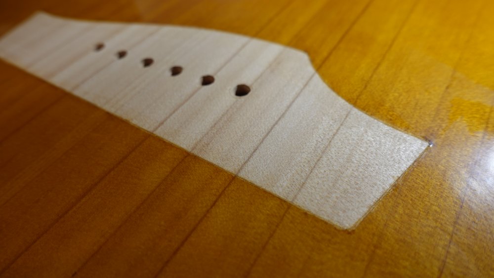
Bridge clamp components |
Gluing the bridge |
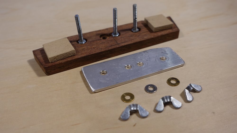
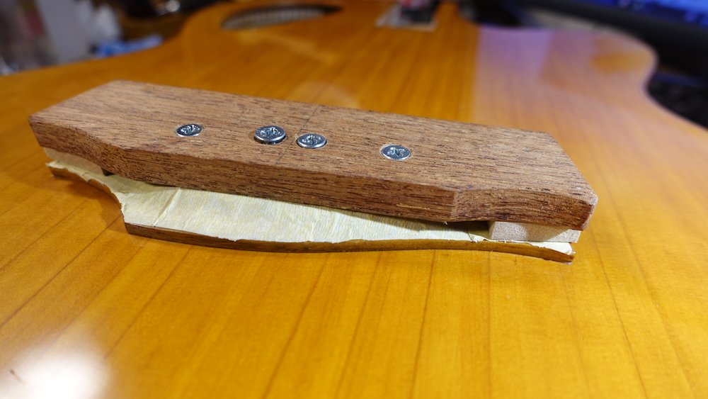
Reaming bridge pin holes to fit |
Completed bridge |
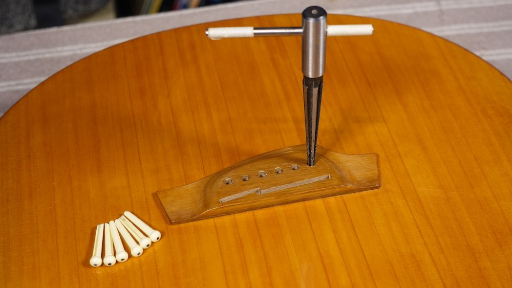
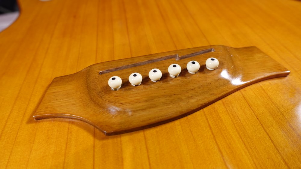
Bolt-on neck option
unfortunately, we levelled the fingerboard extension support before applying finishing to the soundboard
if we tighten the neck support nut, it will stress the fingerboard-neck joint,
and also dig the edges of the fingerboard into the soft soundboard, flaking the finishto correct for this, we need to create some very thin shims, and glue them in
attach neck, check angle - remember for guitars we want to overshoot bridge by 0.5..1.6mm
check if frets are perfectly level (at least until about the 16th fret)
if not level with aluminim sanding bar, then re-crown
Fingerboard support extension shims |
Shims in place, ready for gluing |
Bolt-on neck option at heel |
Bolt-on neck option, interior view |
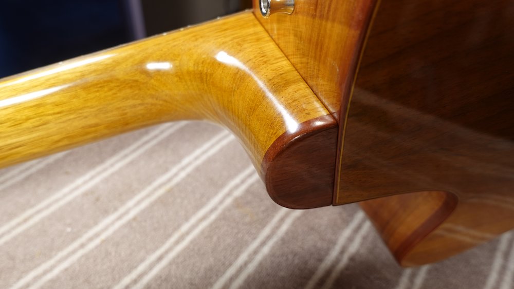
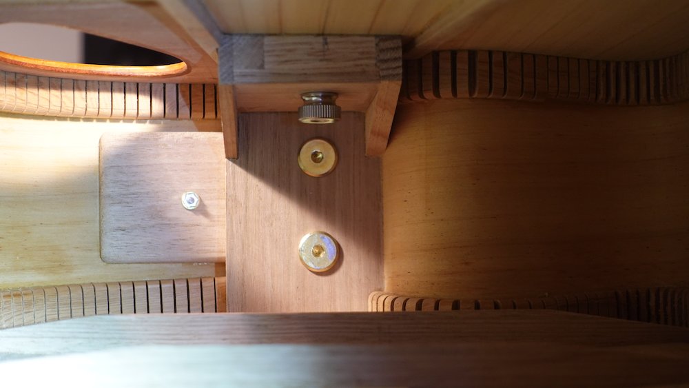
Any finishing to... finish?
If spriting off / car polish / firniture polish was deferred do that now
Attach tuners and fit Straplok
Tuners - duh
But... use a reamer to gently remove any shellac that found its way into the holes, otherwise they will be too tight
Then, when drilling the screw holes, start with a 2.5mm bit (to find centre), then finish with 1.5mm
Staplock tail hole: also duh
Staplock neck hole
Use strap button support glued in after fitting back to sides
Drill hole in body (masking tape)
27mm up from neck, centred
Bolt in place
Strap buttons fitted |
Tuners installed |
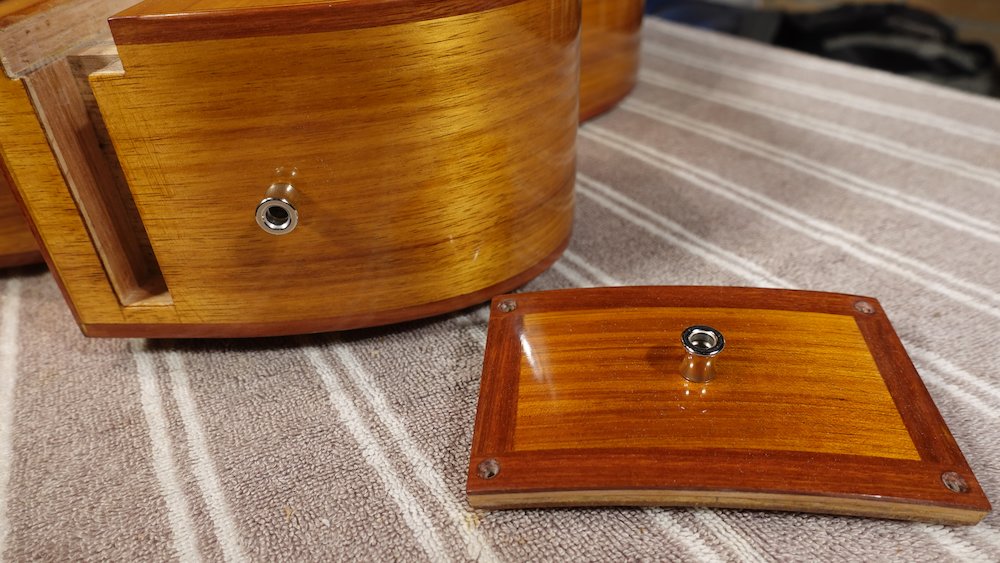
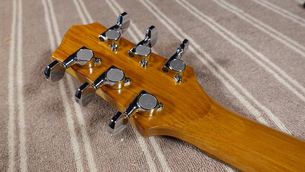
Setup
Cut nut to rough shape
Mark which side of nut is "inward facing"
Start with the nut profile about 2.25mm above the fretboard (we'll be cutting it down later)
Rough in with belt sander, then smooth using neck radius block
Now is a good time to angle the top of the nut so that it is about halfway to the headstock angle. This will make it easier to cut slots that provide a clean break angle for the strings, and avoid "sitar buzz"
For a 6mm nut, a fall of 1mm represents 9.5 degrees, which is pretty good (headstock is 14)
Leave sides a bit proud so they can be blended into neck and truss rod cover (if it reaches the sides)
Mark neck edges and centreline (eventual one will be different)
Mark low-E position 0.5*nut-string-spacing up from centre, then the rest using the tables below
(Alternatively, use a string-spacing steel ruler/template)
Cut slots about 0.5mm deep (we'll be deepening those later too)
Slots should slope/curve down towards the tuners
6-string (equal centers)
String |
Offset |
E1 |
0 |
A |
7.2 |
D |
14.4 |
G |
21.6 |
B |
28.8 |
E2 |
36 |
6-string (hybrid-proportional - recommended)
String |
Offset |
E1 |
0 |
A |
7.4 |
D |
14.7 |
G |
21.9 |
B |
29 |
E2 |
36 |
12-string
String |
Offset |
E1 |
0 |
E2 |
2.3 |
A1 |
7.7 |
A2 |
10 |
D1 |
15.4 |
D2 |
17.7 |
G1 |
23.1 |
G2 |
25.4 |
B1 |
30.8 |
B2 |
33.1 |
E3 |
38.5 |
E4 |
40.8 |
Bass (equal centres)
String |
Offset |
E1 |
0 |
A |
10.75 |
D |
21.5 |
G |
32.25 |
Bass (hybrid-proportional - recommended)
String |
Offset |
E1 |
0 |
A |
11 |
D |
21.6 |
G |
32 |
Bass nut edge clearance (space between outside of nut and edge of strings)
E string half-diameter = 1.4mm
G string half-diameter = 0.7mm
Worked example using 42mm nut width and the above spacings and half-diameter approximations
Segment |
Value |
Cumulative |
E edge clearance: |
3.95 |
3.95 |
E half diameter: |
1.4 |
5.35 |
E-A spacing: |
11 |
16.35 |
A-D spacing: |
10.6 |
26.95 |
D-G spacing: |
10.4 |
37.35 |
G half diameter: |
0.7 |
38.05 |
G edge clearance: |
3.95 |
42 |
Starting work on the nut |
Progress cutting the nut |
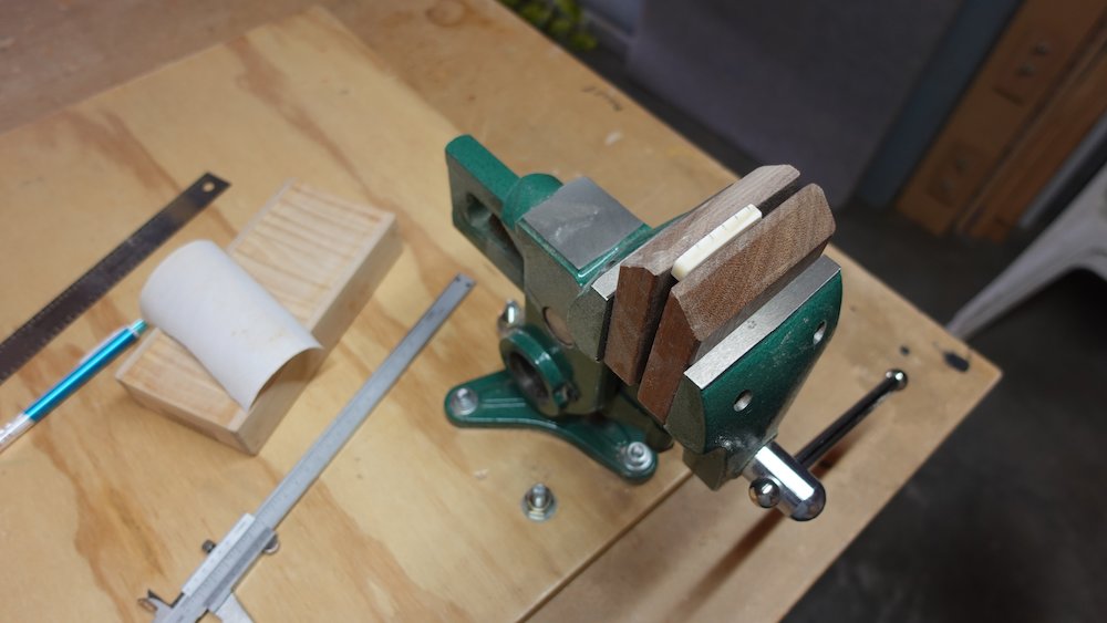
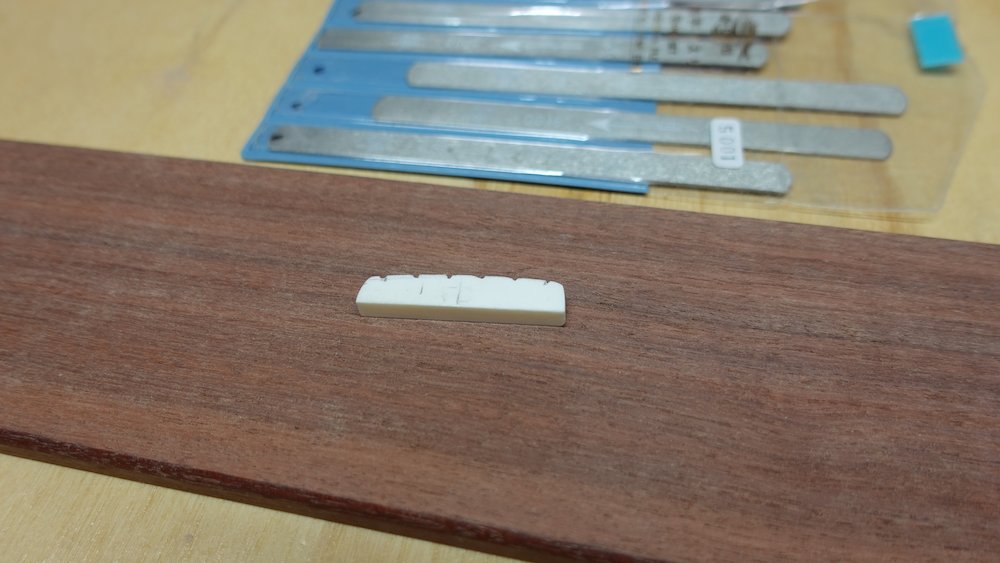
Start work on saddle
Mark which side of saddle is "inward facing"
cut slight radius curve on top of saddle
Take about 2mm off the bass end, 4mm off the treble, leave the middle alone
NB: if using asymmetric fretboard radius, take 2mm off trebleif using neck radius block, use it for smoothing only, saddle radius is a bit different
For split saddle option:
this is a bit more difficult, as the saddle is in two pieces
marking the string positions isn't all that hard,
but making it a nice profile curve requires some estimation
Place in saddle slot, use straightedge to extend fretboard ends to saddle
mark them and use those marks to find string centre
(if this clashes with bridge pin holes, split the difference?)
Mark string positions on saddle
(summary table below, or more complete versions in "Making Bridge" section)
Cut very shallow notches - perfectly horizontal
this is a bit tricker for split saddle option, as the compensation angles are greater
Bass: |
0 |
19.3 |
38.6 |
58 |
||||||||
6-string: |
0 |
11 |
22 |
33 |
44 |
55 |
||||||
12-string: |
0 |
3.2 |
11.4 |
14.6 |
22.8 |
26 |
34.2 |
37. 4 |
45.6 |
48.8 |
57 |
60.2 |
Starting work on the saddle |
Progress cutting the saddle |

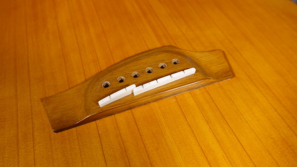
String up guitar
Don't bring it up to pitch - nut and bridge are too high
Get action at nut sorted
For each string
Press just in front of second fret (or use a capo, carefully)
(not between second and third, that may "bend" the string up at the first!)Check clearance at first fret - want "almost touching"
Slightly higher for bass strings
Using shadow of string from desk lamp is useful
A small USB-recharge torch in a desktop mic stand is even better!
Cut slots deeper until the file binds,
Then remove and sand off the top, leaving "semicircle" channels
Use the sliver/shadow method to get first-fret action right
Position a desk lamp / torch behind and above the neck, at about eye level
Look for the shadows of the strings,
More specifically, look for the sliver of light between each string and its shadow
Deepen the slots until those slivers of light are tiny and uniform
A combination of parallax, neck radius and different string diamater will mean that the actual gaps will be higher for the bass strings, with an even graduation to lower for the treble strings
For fretless bass, this is not possible as there are no frets!
Use feeler gauge and aim for 0.5-0.7mm (low E) down to 0.1-0.2mm (G)
Draw a line on the nut across the top of the fingerboard with a sharp pencil
E: leave a tiny gap, A: tinier, D: kiss the line, G: go halfway through it
Double check with feeler gauge, that should get 0.5->0.25mm E->G
First fret action |
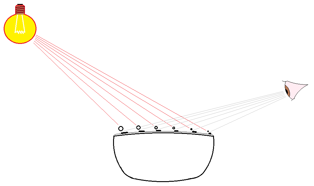
Setting nut action using "sliver/shadow" method |
Nut tidied up and glued in |
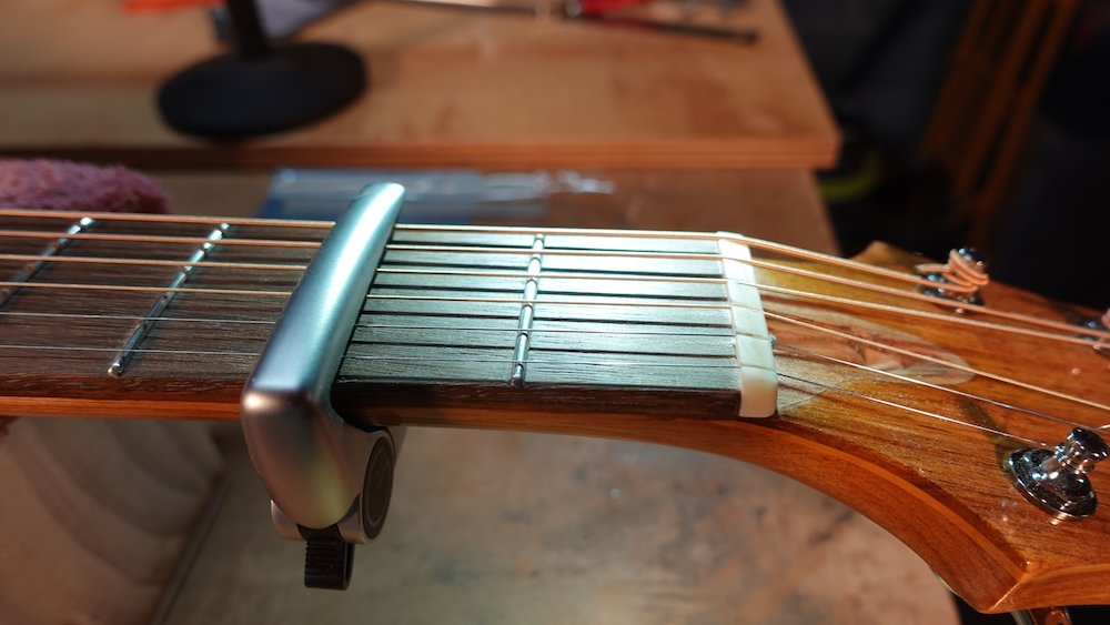
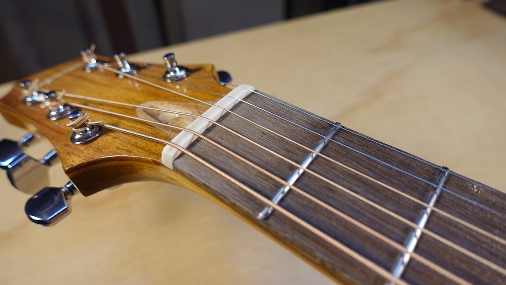
Check neck relief
Tune guitar to D (two semitones down)
If the saddle / 12th-fret action isn't ridiculously high, try tuning to E
Measure relief using straight edge (use fret-slotting templates if ruler too long)
Desired relief
0.25 to 0.3mm (more for bass is probably OK)
Adjust truss rod if necessary
Get action at 12th fret sorted
Stu Mac recommendations (guitar)
Bass E |
Treble E |
(mm) |
(mm) |
|
1st fret |
.023" |
.013" |
0.58mm |
0.33mm |
12th fret |
.090" |
.070" |
2.28mm |
1.78mm |
(These seem awfully low for an acoustic)
Some TalkBass forum numbers (bass)
12th fret|3..6mm|
Good initial targets (guitar)
String |
Safe (mm) |
Brave |
E1 |
2.8 |
2.5 |
A |
2.7 |
2.4 |
D |
2.6 |
2.3 |
G |
2.5 |
2.2 |
B |
2.4 |
2.1 |
E2 |
2.3 |
2.0 |
Good initial target (bass)
First fret (pressing 2..3): 0.55mm?
String |
12th fret(mm) |
E |
4? |
A |
3.6? |
D |
3.3? |
G |
3? |
My first fretless: about 3.5mm lowest three strings
G string a bit lower for "mwah", all others higher for clear tone
My first fretted: about 4.0mm all strings
(Probably could gradate just a little)
Check action at 12th fret for each string using action gauge
Use Excel spreadsheet to track, update and recomment how much to remove
Slacken string, remove bridge pin, file notch deeper
Replace bridge pin, tune up, check action
Slacken all strings, remove saddle, sand to a smooth curve connecting shallow notches
Replace saddle, check intonation
If problems, use a small triangular file to cut slanting V-notches to move string pivot forwards or backwards
If any saddle-buzz, dome the contact points (or two 1/3-way V-notches)
Finish and fit nut semi-permanently
Position nut so strings are correctly centred
Mark edges with sharp pencil
Grind / sand / file so the transitions to the neck are flush and smooth
Fix nut with two drops of CA glue (each side of the truss rod nut)
Attach pick guard and truss rod cover
pick guard: double-sided tape (two narrow strips, top and bottom)
truss rod cover: screw(s)
Current bell-like design can have a single screw 18mm back from point
Measuring action with a curved aluminium action gauge |
Finished split saddle |
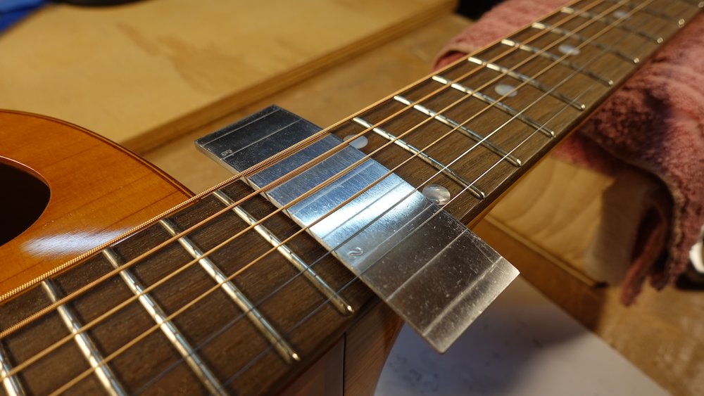
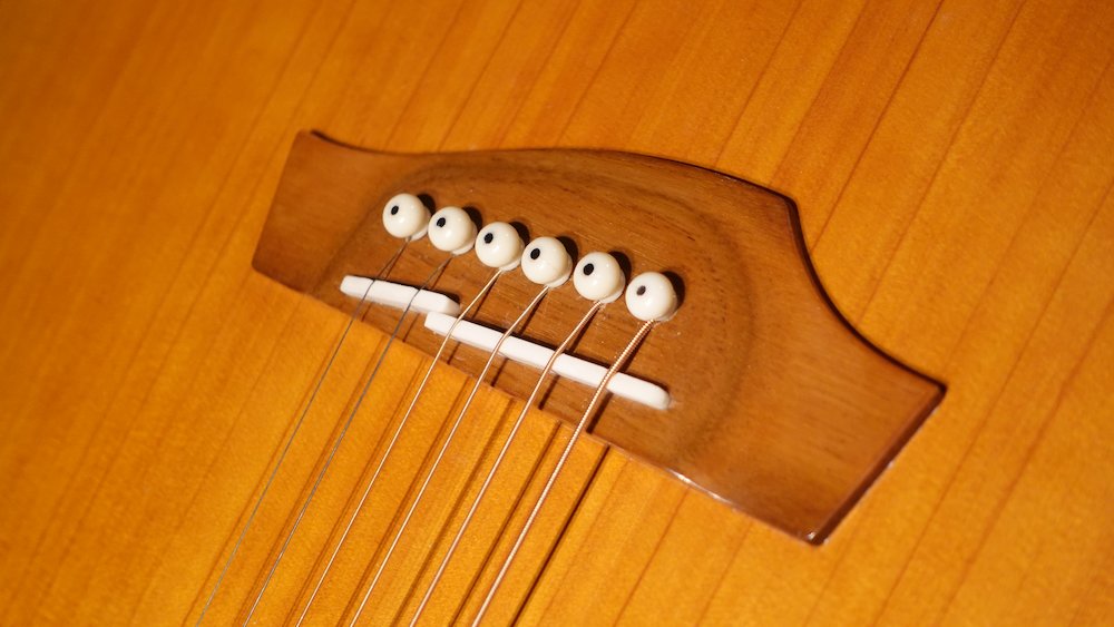
Finished straight saddle |
Preparing to attach pickguard and truss rod cover |
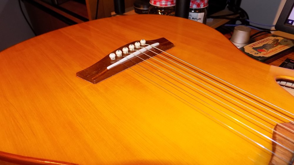
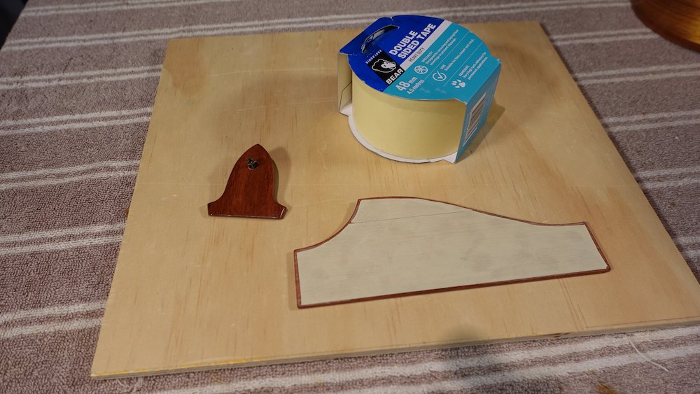
Attaching the pickguard |
Finished pickguard |
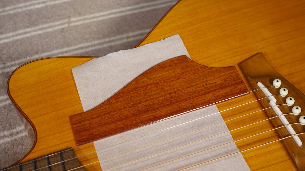
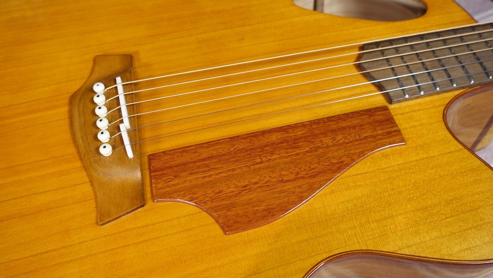
Truss rod cover attached |
The finished access port |
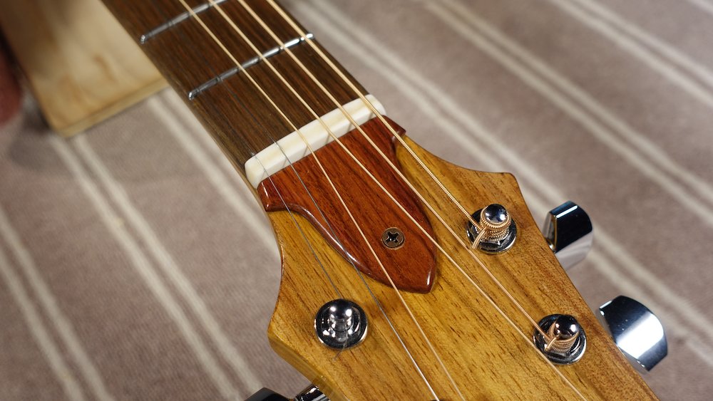
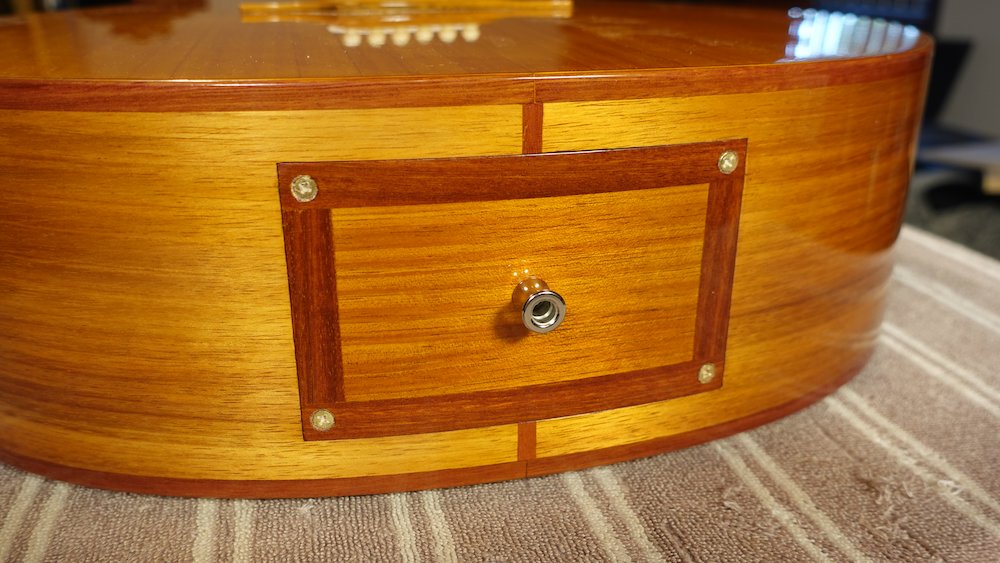
The final guitar, front |
A view of the back |
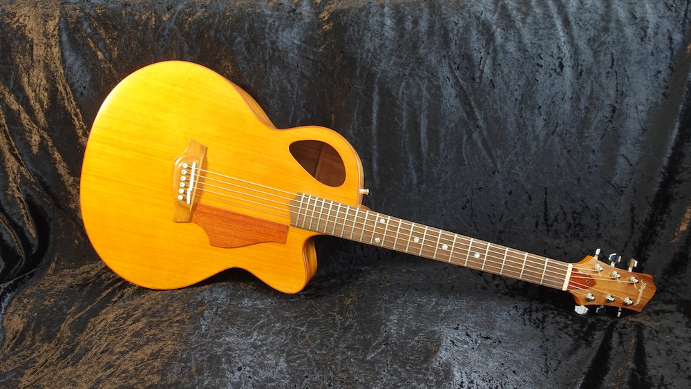
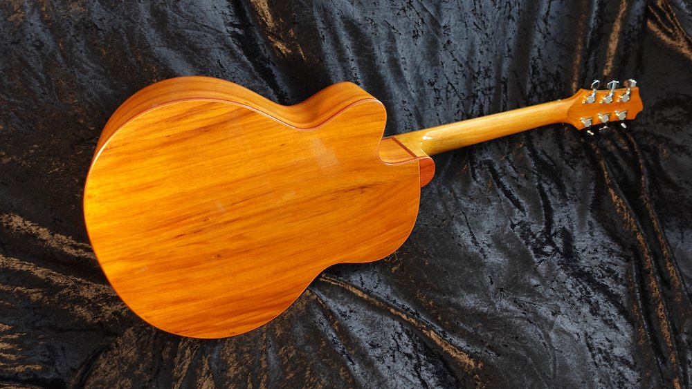
Pickups
My personal preference is for K&K Pure pickups with no onboard electronics. Since this has very high impedance, recording or playing live will require
a pedal like the Zoom AC-3/AC-2
a dedicated acoustic amplifier like those from Boss, Fender, AER, Fishman etc
going directly into the PA/recording interface, with a DI box if the input if required
Since my guitars have no centre sound hole, installation requires
I have built some aluminium installation guides. Note the notches for the wires to slide through, otherwise they'll be permanently "threaded".
The steps are
remove access panel cover, remove strings, put into the two bridge pins
check fit of alminium guide, it should fit up against
cut some bamboo satay skewers to use as clamps, go-bar style
put some wax around the edges of the aluminium guide so superglue squeeze out won't glue it in place
stick the guide to the bridge plate with double-sided sticky tape
position the pickup so the individual piezo elements are accessible and correctly aligned
glue each element separately, as follows
apply some superglue gel to the bridge plate, in the middle of the first guide hole
position the corresponding pickup element in the guide hole and clamp with a satay skewer
do the same for each remaining pickup elements
when the glue has set, detach the guide and unthread from the pickup wires
Drilling for the socket
Measure from the edge of the access panel
Model |
From edge |
From tailpin |
Bass |
140 |
~205 |
GP |
115 |
~180 |
Parlour |
105 |
~170 |
Pickup installation guide |
Satay sticks as clamps |
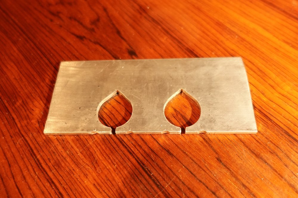
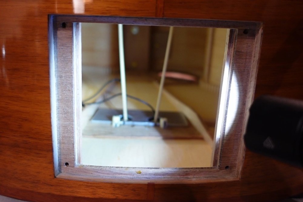
Pickups installed |
Pickup socket installed |
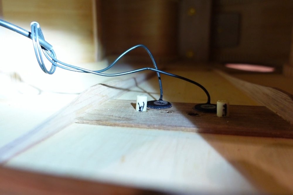
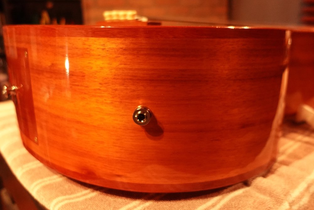
Hardware information
My choice for tuners
Bass: |
Gotoh GB-707C |
6-string: |
Gotoh SG381-01C |
12-string: |
Wilkinson 3+3, SKU TU-141-010 |
My choice for frets
Bass: |
149 |
Jumbo |
.103 x .046 |
2.63 x 1.16 |
FW-001-149 |
Guitar: |
152 |
Oversize Medium |
.092 x .048 |
2.34 x 1.22 |
FW-001-152 |
Build history
Build #1 - fretless bass
most of 2020
over-braced (25++mm A-braces, solid wing braces, too-thick bridge plate)
4mm soundboard, 4mm back(?)
Plays and sounds great
Lessons learnt
double-check before drilling lead jack hole
always turn away from work when pouring alcohol onto French polishing rubber
French polish soundboard before attaching bridge
Build #2 - 12-string 12-body-fret 24" scale Parlour
2021-22
over-braced (25mm A-braces, solid wing braces, thinner bridge plate
3.5mm soundboard, 4mm back
Lessons learnt
Don't pipeline multiple guitar builds this early, lest learning the same lesson three times
Go thinner on those soundboards
Go more aggressive shaping necks
Think carefully about bridge placement (scale length / body fret choices)
Build #3 - 25.5" scale GP
2021-22
slightly over-braced (22mm A-braces, solid wing braces, thinner bridge plate)
3.5mm soundboard, 4mm back
Lessons learnt
Don't pipeline multiple guitar builds this early, lest learning the same lesson three times
Find a way to French polish soundboard before attaching freboard
Build #4 - fretted bass
2022
bracing about right...
3.2mm? soundboard, 4mm back
Lessons learnt
Don't pipeline multiple guitar builds this early, lest learning the same lesson three times
Be more careful about neck angle, and if not, level frets before setup
Protect soundboard before installing (and snipping, and filing) rets
Build #5 - 24.5" 14-fret Parlour
2022
Neck milled to 17mm
3.0mm soundboard, 3.5mm back
much less over-braced
No grain filler on soundboard, experimented with Feast Watson sanding sealer on rest of guitar
Slightly asymmetric bridge due to carelessness drilling pin holes
Lessons learnt
Drill bridge pin holes to achieve repeatable bridge placement before French polishing soundboard
Consider masking bridge and fretboard position 1mm inside actual line to hide transition boundary
Change bridge height calculation (2mm lower?) - excessive grinding down of saddle profile has been a repeated issue
Build #6 - 25.5" 14-fret GP
2022-23
Neck milled to a whisker over 16mm
Access port cover with border to improve appearance
Lessons learnt
if taking sides out of lamination mould early, put them back again after breaking squeeze-out joins
cut cutaway sides longer than marked, trim back as necessary
get serious about verticality of sides before gluing neck block
...
Builds #7,#8 & #9 - a trio of 24.75" 14-fret Fat Parlours, for tonewood comparison
2023-24
Soundboards: (Thinner) Celery-top Pine, King Billy Pine, Huon Pine
Lessons learnt
Lots of grief over bindings
Experimented with two-colour bindings
A few improvements to process, or rather, notes on this page
I really hate hammering frets in over the body
Softwood soundboards are really vulnerable to scratches and dents
Fixed sitar-buzz at nut, still a bit at saddle...
Jarrah sapwood isn't as hard as heartwood
Need to look into extreme saddle height differences
Less 12th-fret action gradient?
Cut fretboard off-centre, so it's thicker at treble side?
Builds #10,#11 - a pair of fretless basses, one my first commission
2024
New timbers: Huon Pine soundboard, Macrocarpa inner side lamination, Spotted Gum fingerboard
Lessons learnt
Bending iron and less extreme back curve can help with bindings
Various reminders added to process steps
Build #12 - experimental build
2024 (actually started before #10 & #11, but was interrupted)
First attempt at bolt-on neck option
Trying out some new timbers: spotted gum, macrocarpa
Stainless steel frets
Several new ideas to improve bindings: less height, gentler back curve, bending iron, superglue
Offset "high point" of radiused fretboard toward treble, so saddle is more symmetric
Shorter nut-to-first-fret distance for improved intonation
Build #13 - second experimental build
2025
Second attempt at bolt-on neck option - refined the steps, much happier with outcome
Trying out some new timbers: king billy pine for kerfed linings - very suitable
Another approach for curved back - strict linear circular profile (too flat in middle section)
Bound fretboard (understated approach) - encountered some issues hammering frets in
Accidentially stumbled on idea of stainless steel for first three frets (may choose this option in future)
All content Copyright 20xx Trevor Magnusson
| × | |